Expandable slotted tubing string and method for connecting such a tubing string

a slotted tubing and expansion method technology, applied in the direction of screw threaded joints, non-disconnectible pipe joints, fluid removal, etc., can solve the problem of bore restriction, and achieve the effect of facilitating sleeve handling

Inactive Publication Date: 2005-02-10
GASOLINEINE WELLSYST
View PDF22 Cites 13 Cited by
  • Summary
  • Abstract
  • Description
  • Claims
  • Application Information

AI Technical Summary

Benefits of technology

[0022] The sleeve may be in the form of longitudinally extending strips of metal. Most preferably, the strips are rectilinear. On expansion, the strips of the sleeve move radially outwardly and separate circumferentially. Initially, that is prior to expansion, the strips may be circumferentially connected, by frangible links 119 such as wire, webs of material or one or more welds, to facilitate sleeve handling.

Problems solved by technology

However, it has been found that, following expansion, the sleeve contracts radially by a significant extent; this creates a restriction in the bore defined by the tubing.

Method used


Image

  • Expandable slotted tubing string and method for connecting such a tubing string
  • Expandable slotted tubing string and method for connecting such a tubing string
  • Expandable slotted tubing string and method for connecting such a tubing string

Examples


Embodiment Construction

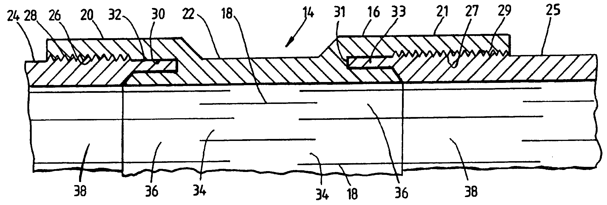
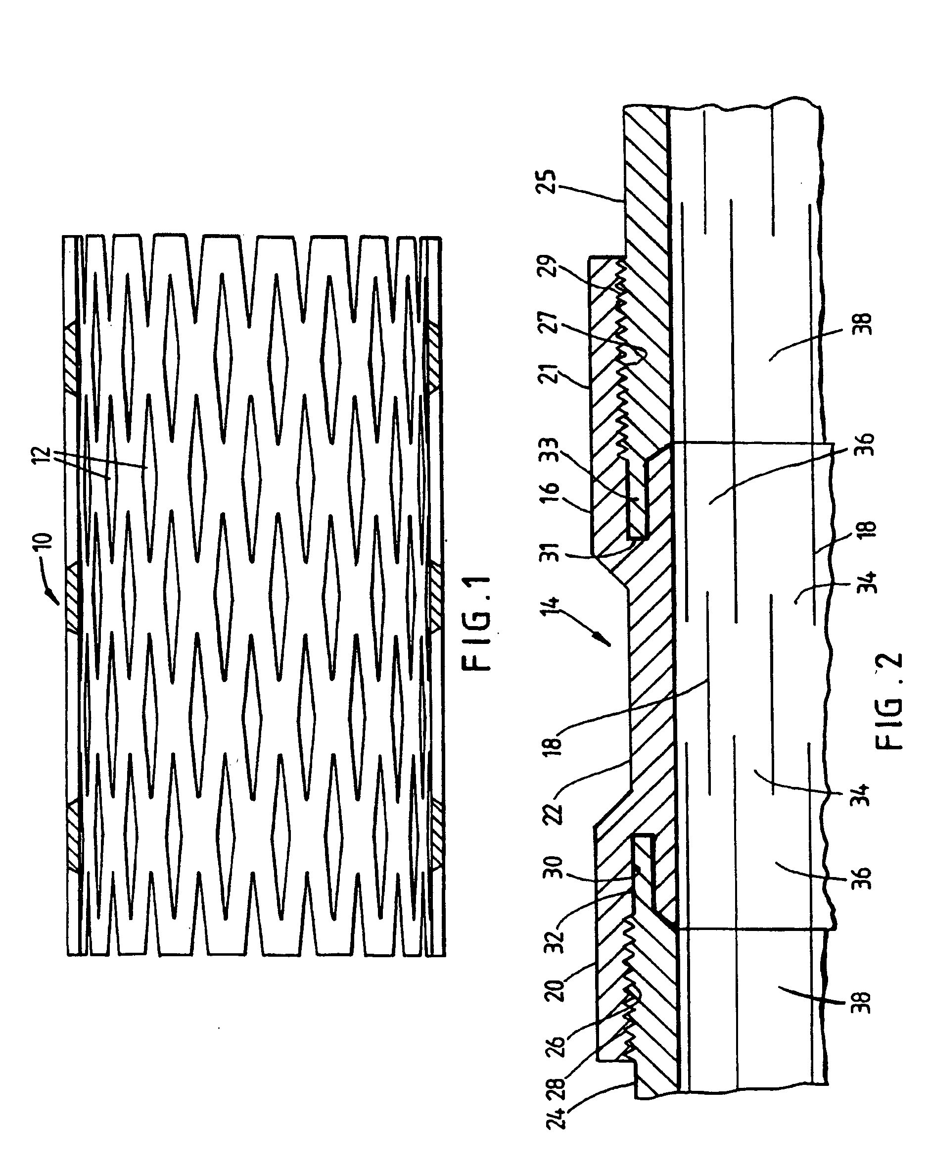
[0032] Reference is first made to FIG. 1 of the drawings, which illustrates a length of expandable tubing 10. In its initial configuration, the tubing 10 is simply a length of pipe in which a series of longitudinal slots 12 have been machined. Applying a radially outward force to the tubing wall, by passing a mandrel through the tubing, causes the tubing to expand such that the slots 12 become diamond-shaped openings.

[0033] The tubing 10 is supplied in lengths suitable for transportation and handling and these are joined to one another on surface to create a tubular string. The assembly 14 illustrated in FIG. 2 of the drawings allows lengths of expandable tubing 10 to be connected to form a string, as will now be described.

[0034] The assembly 14 comprises a tubular connector 16 defining overlapping longitudinal slots 18, the connector 16 comprising end portions 20, 21 and an intermediate portion 22. The slots 18 extend over the whole length of the connector 16, but the only slot o...


PUM

PropertyMeasurementUnit
lengthsaaaaaaaaaa
lengthaaaaaaaaaa
diameteraaaaaaaaaa

Abstract

An expandable tubing assembly comprises a tubular connector defining overlapping longitudinal slots, the connector comprising end portions and an intermediate portion. The slots extend over the whole length of the connector, but the only slot overlap occurs in the intermediate portion. The assembly further comprises lengths of expandable tubing defining overlapping longitudinal slots and having end portions defining nodes between and beyond the ends of the tubing slots. Tubing threads are formed on the end most tubing nodes. The connector end portions define threads and are coupled with the threads formed on the nodes of the respective end portions of the tubing lengths.

Description

CROSS-REFERENCE TO RELATED APPLICATIONS [0001] This application is a continuation of U.S. patent application Ser. No. 09 / 381,508, filed Sep. 21, 1999, which is the National Stage of International Application No. PCT / GB98 / 00863, filed on Mar. 20, 1998 and published under PCT Article 21(2) in English, and claims priority of United Kingdom Applications No. 9705928.1 filed on Mar. 21, 1997 and No. 9723338.1 filed on Nov. 4, 1997. All the above referenced patent applications are incorporated by reference in their entireties.BACKGROUND OF THE INVENTION [0002] 1. Field of the Invention [0003] This invention relates to a connector, and in particular to a connector forming part of an expandable tubing assembly. The invention also relates to a method of connecting lengths of expandable tubing. [0004] 2. Description of the Related Art [0005] W093\25800 describes expandable tubing defining overlapping longitudinal slots. On expansion of the tubing, by pushing or pulling a mandrel through the tu...

Claims


Application Information

Patent Timeline
Patent Type & Authority Applications(United States)
IPC IPC(8): E21B17/08E21B43/08E21B43/10F16L13/14F16L13/16
CPCB21D39/04Y10T29/49893E21B43/082E21B43/086E21B43/103E21B43/106E21B43/108F16L13/147F16L13/168F16L15/006F16L25/08Y10T403/5761Y10T29/49911Y10T403/557Y10T29/4994Y10T29/49938Y10T403/5781E21B17/08
Inventor METCALFE, PAUL DAVID
Owner GASOLINEINE WELLSYST
Why Eureka
Try Eureka