Digital light processing projection system and projection method of the same

Inactive Publication Date: 2005-02-10
DELTA ELECTRONICS INC
View PDF5 Cites 5 Cited by
  • Summary
  • Abstract
  • Description
  • Claims
  • Application Information

AI Technical Summary

Benefits of technology

[0019] The invention has the advantages of: 1) shortening a back focal distance of the projection system; 2) effectively mai

Problems solved by technology

However, excessive optical stops may lower lumen of the projection system under a light state.
Under such circu

Method used


Image

  • Digital light processing projection system and projection method of the same
  • Digital light processing projection system and projection method of the same
  • Digital light processing projection system and projection method of the same

Examples


Embodiment Construction

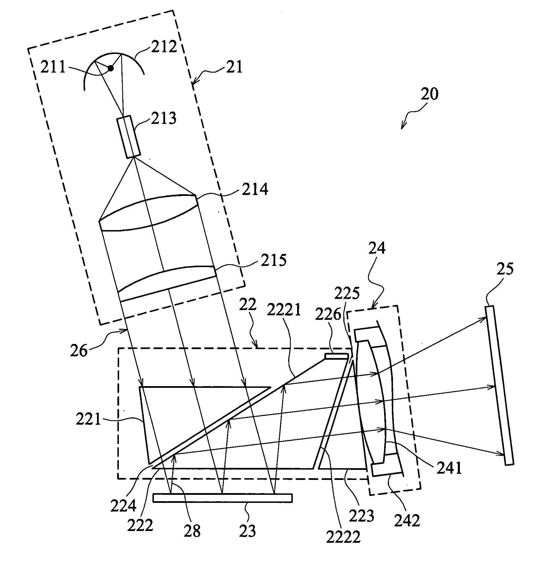
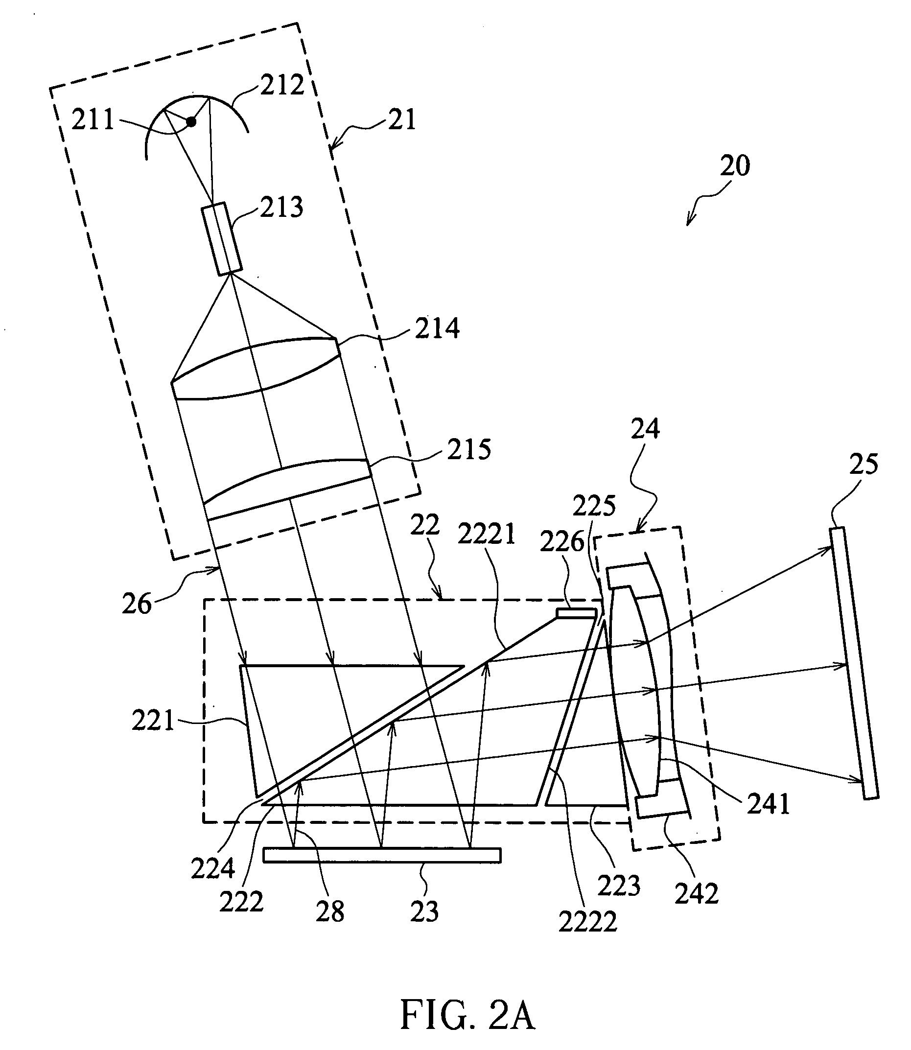
[0026] Referring to FIGS. 2A and 2B, a digital light processing (DLP) projection system 20 according to a first embodiment of the invention includes an illuminating device 21, a prism set 22, an optical-path-switching element 23, and a projection device 24. The prism set 22 is arranged between the illuminating device 21, the optical-path-switching element 23, and the projection device 24. Detailed descriptions for the elements of the DLP projection system 20 are given below.

[0027] The illuminating device 21 in this embodiment has a light source 211, a lampshade 212, a light guide 213, a relay lens 214 and a light collector lens 215. The configuration of the light source 211, the lampshade 212 and the light guide 213 enables light beams emitted by the light sources 211 to enter the light guide 213 and enter the prism set 22 after passing through the relay lens 214 and the collector lens 215. In addition, a plurality of micro-mirrors (not shown) provided on the optical-path-switching...


PUM


Abstract

A digital light processing projection system includes an illuminating device, an optical-path-switching element, a projection device and a prism set. The prism set is arranged between the illuminating device, the optical-path-switching element and the projection device and has a plurality of prisms in which an air gap existing between any two adjacent prisms. According to the invention, a light beam output from the illuminating device directly passes through the prisms and air gaps before being received by the optical-path-switching element. Under a first state, a light beam reflected from the optical-path-switching element is totally reflected at an interface between one of the prisms and one of the air gaps before being received by the projection lens. Under a second state, a light beam reflected from the optical-path-switching element is totally internal reflected back and forth within a prism being adjacent to the optical-path-switching element and is absorbed by a light absorbing material.

Description

BACKGROUND OF THE INVENTION [0001] (a) Field of the Invention [0002] The invention relates to an optical projection system and, more particularly, to a digital light processing (DLP) projection system and a projection method of the same. [0003] (b) Description of the Related Art [0004] The Digital light processing (DLP) technique has been developed by Texas Instrument since 1987. In a DLP projection system, an optical element called digital micro-mirror device (DMD) is utilized. On the digital micro mirror device there are thousands of micro-mirrors for reflecting light beams onto a screen to form an image. Each of these micro-mirrors has independent driving electrode, support post and steering shaft. When the DLP projection system is under a light state, light beams projected onto the micro-mirrors are reflected into a projection lens by these micro-mirrors and then focused on a screen. When the DLP projection system is under a dark state, these micro-mirrors are driven by applying...

Claims


Application Information

Patent Timeline
IPC IPC(8): G02B27/18G02B5/04G03B21/00G03B21/28
CPCG03B21/00G03B21/008
Inventor CHANG, SEANHUANG, SEAN
Owner DELTA ELECTRONICS INC
Why Eureka
Try Eureka