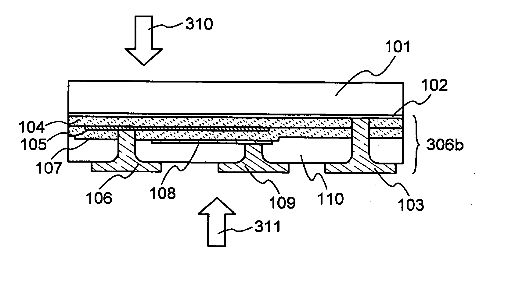
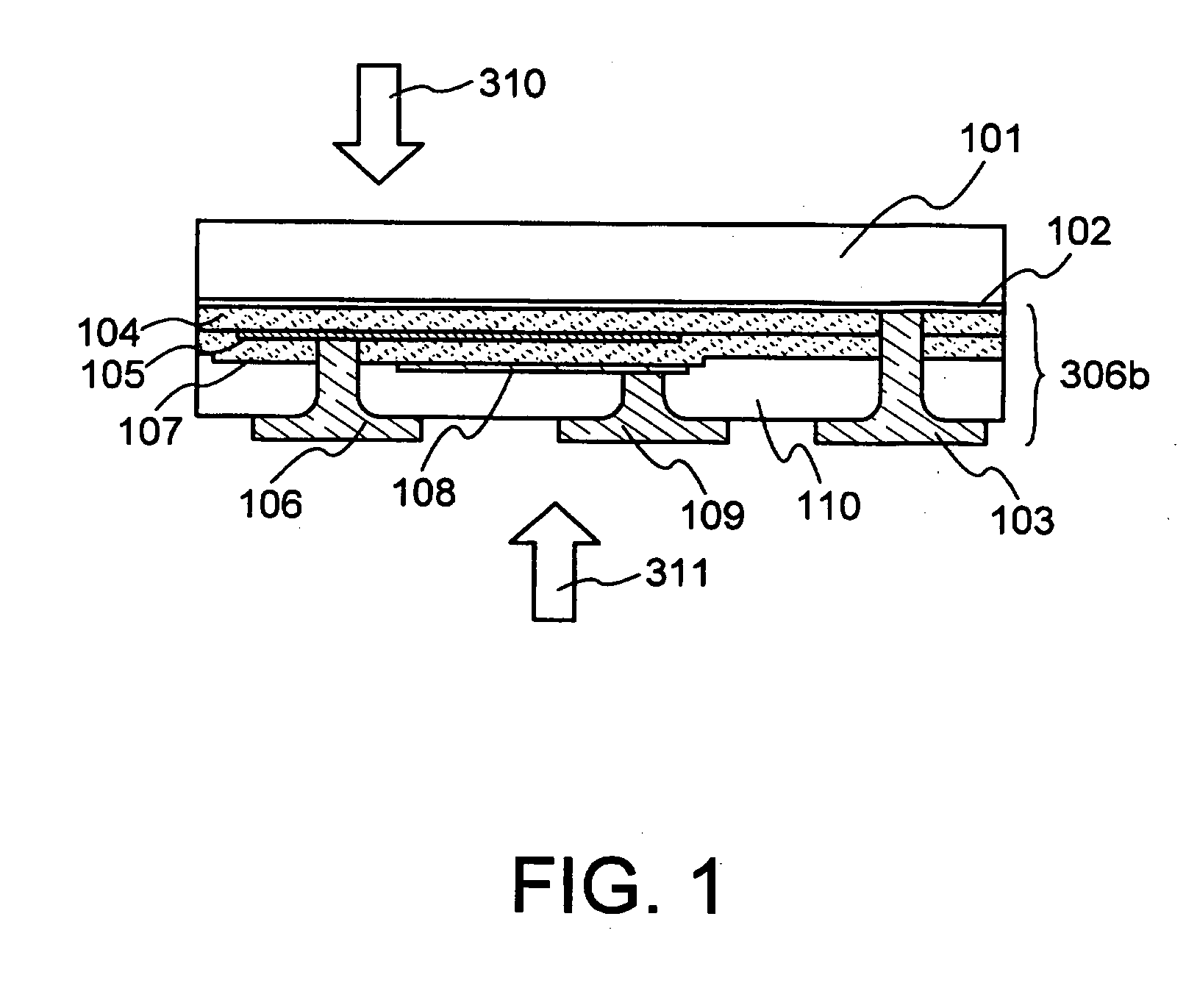
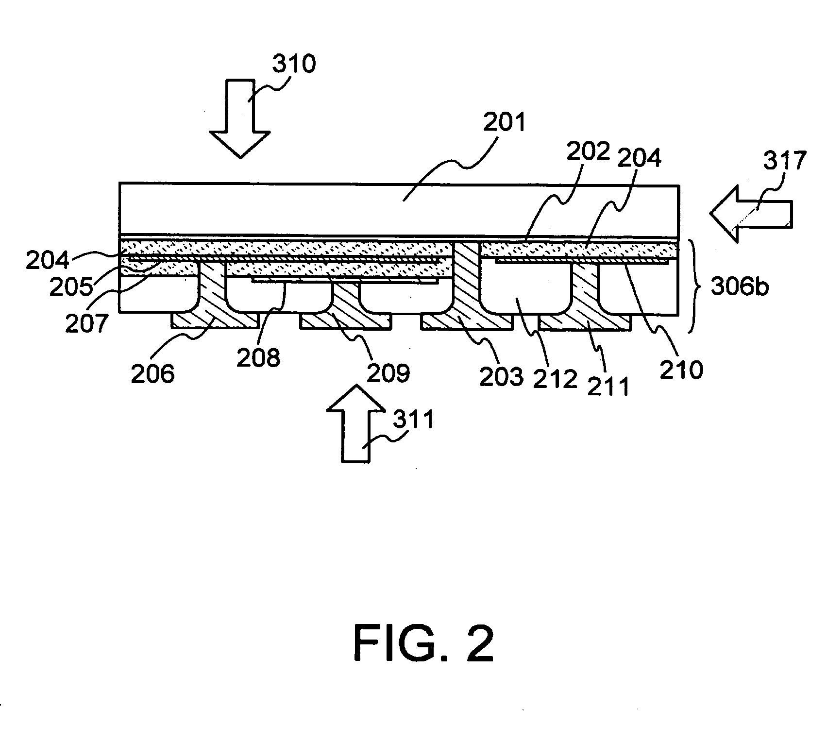
Multidirectional photodetector, a portable communication tool having thereof and a method of displaying
a multi-directional, portable technology, applied in the field of photodetectors, can solve the problems of deterioration and degree of deterioration of the electromechanical element, and achieve the effects of suppressing the power consumption of displaying, reducing the power consumption of consuming, and improving visibility
- Summary
- Abstract
- Description
- Claims
- Application Information
AI Technical Summary
Benefits of technology
Problems solved by technology
Method used
Image
Examples
embodiment mode 1
[0057]FIG. 5 is a schematic view of a portable telephone according to the invention, FIG. 5(A) is a perspective view in a state where the housings are opened and FIG. 5(B) is a perspective view in a state where the housings are closed, i.e., a perspective view as viewed from the side of a first housing 800a provided with a second display portion 802.
[0058] The portable telephone has two housings 800a and 800b which are connected together via a hinge 509, and which can be opened and closed with the hinge 509 as a center.
[0059] The first housing 800a is provided with a first display portion 801, a second display portion 802, speakers 806a and 806b, an antenna 807, a camera lens 808, a first daylight hole 810, a second daylight hole 811, a lamp 814 and the like.
[0060] The second housing 800b includes operation buttons 803, operation buttons 804 provided on the side surface of the portable telephone, a microphone 805, an open / closure detector switch 812, a headphone terminal cover 81...
embodiment mode 2
[0109] This embodiment mode explains the photodetector having a structure different from that of the embodiment mode 1, a portable communication tool having the same, and a method of displaying. In this embodiment mode, too, there is used a portable telephone as a representative example of the portable communication tools, and the same portions as those of the embodiment mode 1 are denoted by the same reference numerals but are not described in detail.
[0110]FIG. 4 is a sectional view of the embodiment mode along (a)-(a′) of FIG. 5(B). Like in the embodiment mode 1, the first display portion 801 and the second display portion 802 are secured to the wiring substrate 301 using the adhesives 304 and 305. The first display portion 801 is formed by the substrate 801a and the light-emitting region 801b provided thereon. Similarly, the second display portion 802 is formed by the substrate 802a and the light-emitting region 802b provided thereon. The first display portion 801 emits the firs...
embodiment mode 3
[0144] This embodiment mode explains about the foldable portable communication tool having the photodetector installed at a different place. This embodiment mode, too, deals with a portable telephone as a representative example of the portable communication tools, and the same portions as those of the embodiment mode 1 are denoted by the same reference numerals but are not described in detail.
[0145] In this embodiment mode, described is a portable telephone in which the second housing of the portable telephone is provided with the photodetector including the detector element for controlling the brilliance of the first display portion and the detector element for detecting the intensity of illumination on the side of the display portion, which are connected in parallel.
[0146]FIG. 6 is a view schematically illustrating the foldable portable telephone according to the present invention, wherein FIG. 6(A) is a perspective view in an open state, and FIG. 6(B) is a perspective view in a...
PUM
 Abstract
Description
Claims
Application Information
 - R&D
- Intellectual Property
- Life Sciences
- Materials
- Tech Scout
- Unparalleled Data Quality
- Higher Quality Content
- 60% Fewer Hallucinations
Browse by: Latest US Patents, China's latest patents, Technical Efficacy Thesaurus, Application Domain, Technology Topic, Popular Technical Reports.
© 2025 PatSnap. All rights reserved.Legal|Privacy policy|Modern Slavery Act Transparency Statement|Sitemap|About US| Contact US: help@patsnap.com


