
Exhaust gas control apparatus and control method for exhaust gas control apparatus

a control apparatus and control method technology, applied in mechanical apparatus, engine components, machines/engines, etc., can solve the problems of difficult to collect this particulate matter downstream, large particle diameter of particulate matter that has once been detached, and not always uniform deposit of particulate matter

Active Publication Date: 2018-11-27
TOYOTA JIDOSHA KK
View PDF3 Cites 0 Cited by
  • Summary
  • Abstract
  • Description
  • Claims
  • Application Information

AI Technical Summary

Benefits of technology

[0005]The disclosure provides an exhaust gas control apparatus capable of restraining particulate matter from being detached as a result of the bias in deposition of the collected particulate matter, and a control method for the exhaust gas control apparatus.
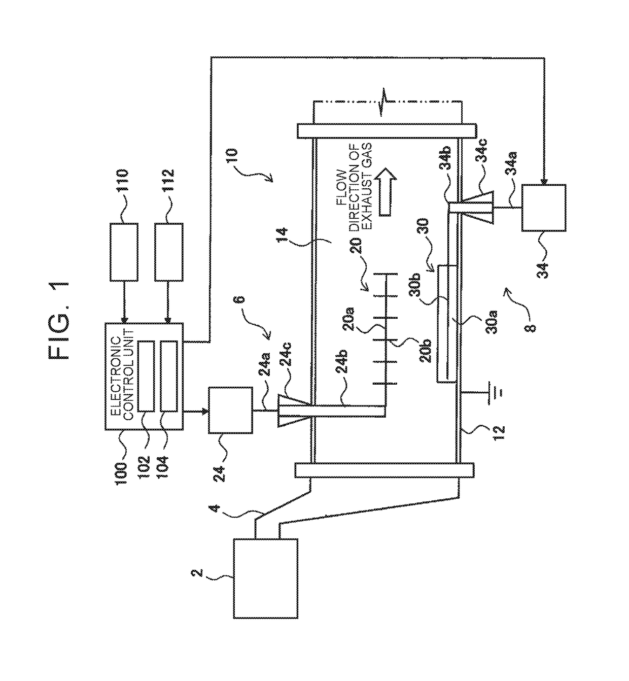
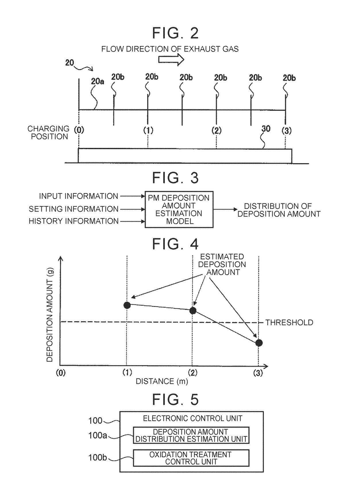
[0008]In the aforementioned configuration, the input information is information on a condition of the treated exhaust gas. The setting information is information on the setting on the side of the device for collecting exhaust gas. The history information is information on the history of the oxidation treatment carried out so far, namely, information on a decrease in the deposition amount through the oxidation treatment. Besides, the deposition amount mentioned herein is a deposition amount per predetermined length in the flow direction of exhaust gas. The threshold is, for example, an upper limit of the range of the deposition amount where detachment of the particulate matter is confined within a permissible range. According to this configuration, when the deposition of the collected particulate matter is biased and the deposition amount exceeds the threshold somewhere due to the bias, the oxidation treatment is carried out by the oxidation treatment device even in the case where the deposition amount is sufficiently smaller than the threshold as a whole. Thus, the particulate matter is restrained from being detached as a result of the bias in deposition of the collected particulate matter.
[0009]In the exhaust gas control apparatus, the oxidation electrode may be constituted of a plurality of partial electrodes that are aligned in the flow direction of exhaust gas. The oxidation treatment device may be configured to be able to carry out the oxidation treatment individually for each of the partial electrodes. According to this configuration, an AC voltage can be applied only to a location where the oxidation treatment is desired to be carried out, so the amount of electric power consumption can be held small. In the exhaust gas control apparatus, the electronic control unit may be configured to carry out the oxidation treatment by that one of the partial electrodes which corresponds to a region where the deposition amount exceeds the threshold (in other words, the electronic control unit may be configured to carry out the oxidation treatment by one of the partial electrodes, the one of the partial electrodes corresponding to a region where the deposition amount exceeds the threshold). According to this, only the location where the particulate matter may be detached can be subjected to the oxidation treatment, so the particulate matter can be restrained from being detached while holding the amount of electric power consumption small.
[0010]In the exhaust gas control apparatus, the charging electrode may include a plurality of discharge portions that are aligned in the flow direction of exhaust gas, and the dust collection device may be configured to be able to carry out discharge individually for each of the discharge portions. In this case, the electronic control unit may be further equipped with a charging position control unit that changes a charging position on the oxidation substrate by changing over that one of the discharge portions which is to be discharged. The distribution of the deposition amount of the particulate matter on the oxidation matter can also be changed by changing the charging position on the oxidation substrate. In the exhaust gas control apparatus, the electronic control unit may be configured to change over that one of the discharge portions which is to be discharged, in accordance with a change in the distribution of the deposition amount. For example, the amount of bias in deposition of the particulate matter in the flow direction of exhaust gas can be reduced by, for example, changing over the discharge portion to a position where the deposition amount on the oxidation substrate is small.
[0011]In the exhaust gas control apparatus, the electronic control unit may be configured to carry out the oxidation treatment by that one of the partial electrodes which corresponds to a region where the deposition amount exceeds the threshold. The electronic control unit may be configured to change over that one of the discharge portions which is to be discharged in such a manner as to shift the charging position from a position of that one of the partial electrodes for which the oxidation treatment is carried out to another position, when a deposition speed of the particulate matter at the position of that one of the partial electrodes for which the oxidation treatment is carried out is higher than an oxidation speed of the particulate matter. According to this, the deposited particulate matter can be restrained from being detached due to a delay in the oxidation treatment.

Problems solved by technology

However, the particulate matter is not always uniformly deposited, and the deposition of the particulate matter may be biased.
The particulate matter that has once been detached has a large particle diameter and becomes qualitatively difficult to charge.
It is therefore difficult to collect this particulate matter again downstream.

Method used


Image

  • Exhaust gas control apparatus and control method for exhaust gas control apparatus
  • Exhaust gas control apparatus and control method for exhaust gas control apparatus
  • Exhaust gas control apparatus and control method for exhaust gas control apparatus

Examples


first embodiment

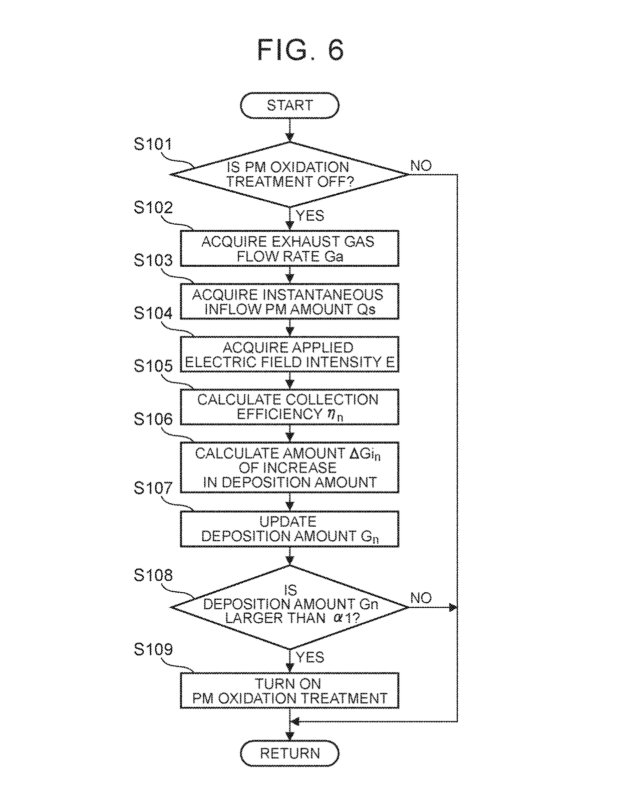
[0038]Next, the outline of oxidation treatment control will be described. It is useful to continuously collect the PM by the dust collection device 6 while exhaust gas containing the PM is discharged from the internal combustion engine 2. On the other hand, the oxidation treatment of the PM does not need to be always carried out by the oxidation treatment device 8. The oxidation treatment may be carried out after collecting a certain amount of PM. This is because the consumption energy increases and the fuel economy of the entire vehicle deteriorates as the frequency with which the oxidation treatment is carried out is increased. It should be noted, however, that the PM deposited on the oxidation substrate 30 is detached and flows out from the exhaust gas control apparatus 10 if the oxidation treatment is carried out at a wrong timing.

[0039]In the present embodiment, instead of the total deposition amount of PM deposited on the oxidation substrate 30, the deposition amount of PM in...

second embodiment

[0082]A concrete example of charging position control will now be described through the use of FIG. 11. FIG. 11 depicts an example in which that one of the discharge portions 20b which is to be discharged is changed over among the three discharge portions 20b corresponding to the charging positions 1, 2, and 3 respectively. Besides, in this concrete example, oxidation treatment control described in the second embodiment, namely, the control of carrying out the oxidation treatment individually for each of the partial electrodes that are aligned in the flow direction of exhaust gas is combined with charging position control.

[0083]In STEP 1 shown in FIG. 11, the discharge portion 20b corresponding to the charging position 1 is discharged. Due to this discharge, PM is deposited in the region close to the charging position 1 on the oxidation substrate 30. In STEP 2 following STEP 1, the oxidation treatment is carried out by the partial electrode corresponding to the charging position 1, ...


PUM


Abstract

An exhaust gas control apparatus includes a dust collection device, an oxidation treatment device, and an ECU. The dust collection device applies a DC voltage between a charging electrode and a counter electrode, and collects particulate matter on an oxidation substrate. The ECU estimates a distribution of a deposition amount of the particulate matter deposited on the oxidation substrate in a flow direction of exhaust gas, based on input information including at least a flow rate of exhaust gas and a mass of particulate matter in exhaust gas, setting information including at least an electric field intensity between the charging electrode and the counter electrode, and history information on the oxidation treatment. The ECU carries out the oxidation treatment when the deposition amount of at least a part of the deposited particulate matter exceeds a threshold.

Description

CROSS-REFERENCE TO RELATED APPLICATIONS[0001]This application claims priority to Japanese Patent Application No. 2017-086424 filed on Apr. 25, 2017, which is incorporated herein by reference in its entirety including the specification, drawings and abstract.BACKGROUND1. Technical Field[0002]The disclosure relates to an exhaust gas control apparatus that purifies exhaust gas by collecting the particulate matter contained in exhaust gas and subjecting the collected particulate matter to an oxidation treatment, and a control method for the exhaust gas control apparatus.2. Description of Related Art[0003]In each of Japanese Patent Application Publication No. 2012-170869 (JP 2012-170869 A) and Japanese Patent Application Publication No. 2016-107173 (JP 2016-107173 A), there is disclosed an exhaust gas control apparatus that subjects the particulate matter contained in exhaust gas to an oxidation treatment with the aid of discharge plasma. In concrete terms, this kind of exhaust gas contr...

Claims


Application Information

Patent Timeline
Patent Type & Authority Patents(United States)
IPC IPC(8): F01N3/01F01N9/00
CPCF01N9/002F01N3/01F01N2250/08F01N2240/28F01N2240/38F01N2240/04H05K13/04F01N3/0275B03C3/49B03C3/88F01N3/103F01N11/00F01N2900/1606Y02T10/12Y02T10/40B03C3/34
Inventor SUGIMOTO, KAZUHIRO
Owner TOYOTA JIDOSHA KK
Learn More