
Measurement device, measurement system, and measurement method for measuring particle and gas

a measurement device and measurement system technology, applied in the direction of instruments, material thermal conductivity, material analysis, etc., can solve the problems of large device size and large electric power consumption, and achieve the effects of small electric power consumption, large electric power consumption, and high measurement accuracy

Active Publication Date: 2018-07-10
FUJITSU LTD
View PDF15 Cites 0 Cited by
  • Summary
  • Abstract
  • Description
  • Claims
  • Application Information

AI Technical Summary

Benefits of technology

The patent text proposes a gas measurement device that is small and consumes small electric power. It includes a gas detection unit made of semiconductor material where a gas can be adsorbed, resulting in changes in electric resistance. This device has advantages in that it can be easily integrated into various applications and can provide accurate gas measurement with low power consumption.

Problems solved by technology

However, although the β-ray absorption type measurement device in accordance with the official method has high measurement accuracy, the device is large and consumes a large amount of electric power.

Method used


Image

  • Measurement device, measurement system, and measurement method for measuring particle and gas
  • Measurement device, measurement system, and measurement method for measuring particle and gas
  • Measurement device, measurement system, and measurement method for measuring particle and gas

Examples


first embodiment

[0044]Hereinafter, a preferable first embodiment of a measurement device disclosed in the present description will be illustrated with reference to the drawings. Note that the technical scope of the present invention is not limited to the embodiments herein but extends to the inventions as recited in the claims as well as equivalents thereof.

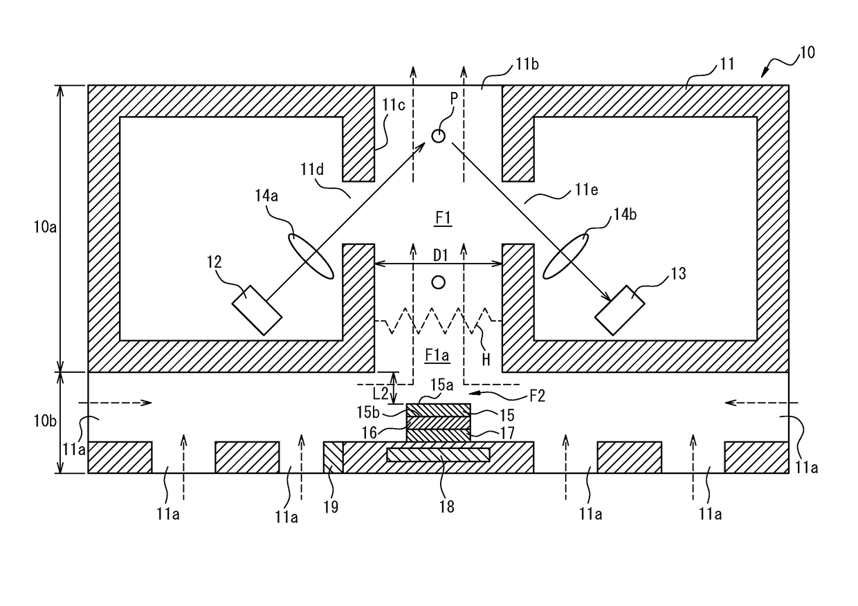
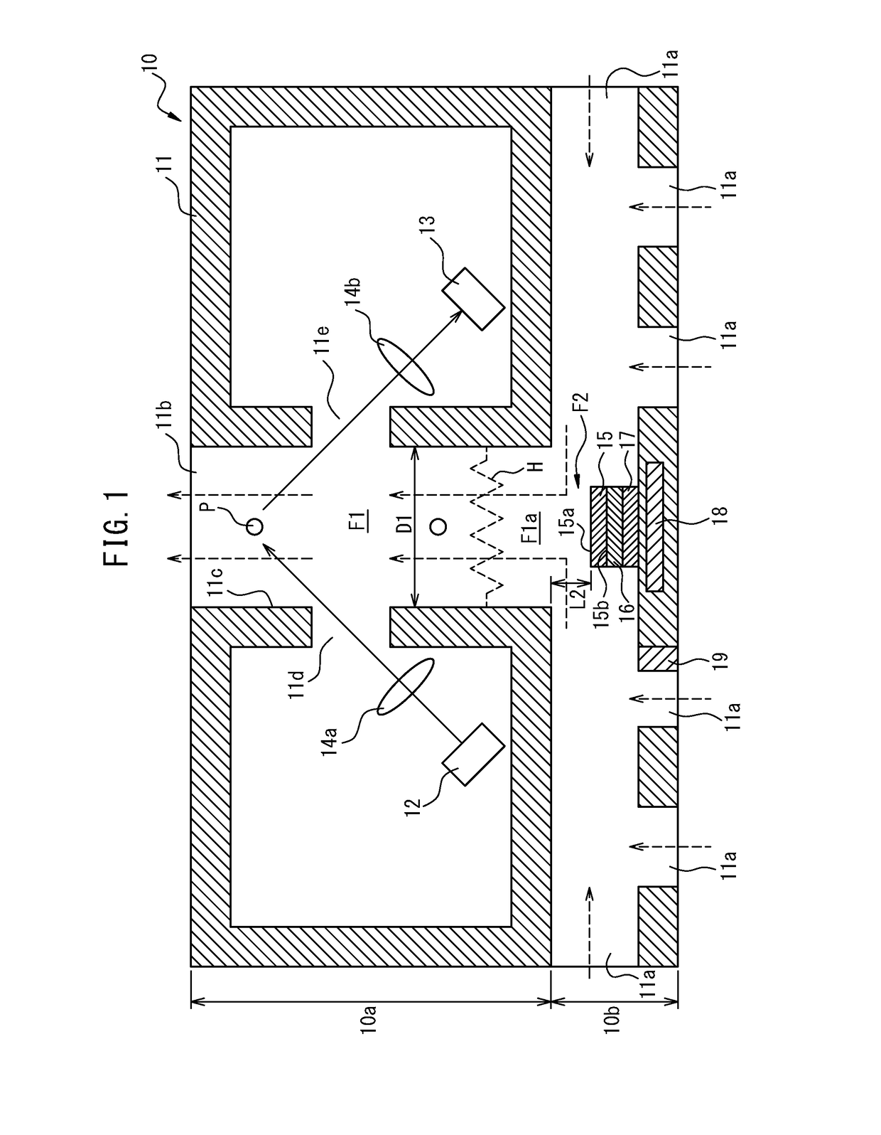
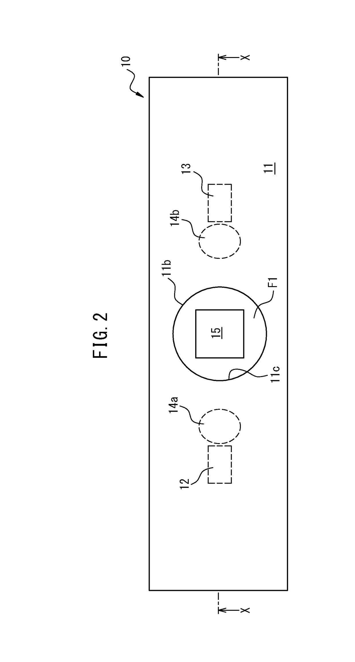
[0045]FIG. 1 is a cross-sectional view of the first embodiment of the measurement device disclosed in the present description. FIG. 2 is a plan view of the first embodiment of the measurement device disclosed in the present description. FIG. 1 is the cross-sectional view taken along a line X-X of FIG. 2.

[0046]A measurement device 10 according to the present embodiment measures particles and a gas in the air.

[0047]The measurement device 10 includes a particle measurement unit 10a which measures a particle concentration and a particle size distribution in the air and a gas measurement unit 10b which measures a concentration of a predetermined gas ...

third embodiment

[0125]FIG. 10 is a cross-sectional view of the measurement device disclosed in the present description.

[0126]The measurement device 10 according to the present embodiment includes a thermoelectric conversion unit 20 to which electric power is supplied, thereby absorbing heat in the exterior and radiating heat in such a manner as to heat the second surface 15b of the gas detection unit 15.

[0127]The thermoelectric conversion unit 20 includes a first electrode layer 21, a second electrode layer 22, and a thermoelectric conversion element 23. The thermoelectric conversion element 23 is disposed between the first electrode layer 21 and the second electrode layer 22 and is supplied with the electric current, thereby transferring heat on a side of a second electrode layer 22 to a first electrode layer side. As the thermoelectric conversion element 23, for example, a Peltier element can be used.

[0128]To the first electrode layer 21 and the second electrode layer 22, the unillustrated contro...


PUM

PropertyMeasurementUnit
particle sizeaaaaaaaaaa
electric poweraaaaaaaaaa

Abstract

A measurement device includes a first flow passage, a heating unit provided on one end side of the first flow passage, a gas detection unit provided on one end side of the first flow passage and capable of detecting a gas through heat applied from the heating unit, and a particle measurement unit which optically measures, at an upper side than the heating unit of the first flow passage, particles passing through the first flow passage.

Description

[0001]This application is based upon and claims the benefit of priority of the International Application PCT / JP2014 / 069702, filed on Jul. 25, 2014 and designated the U.S. the entire contents of which are incorporated herein by reference.FIELD[0002]The present invention relates to a measurement device, measurement system, and measurement method for measuring particle and gas.BACKGROUND[0003]In recent years, in conjunction with development of industries and multipoint progress of manufacturing industries, air pollution on a global scale has been feared. For example, respiratory diseases due to particulate matter in suspension (Suspended Particulate Matter: SPM or particulate matter: PM 2.5) or ground level ozone can be mentioned. According to an environmental outlook to 2050 published in 2012 by the Organization for Economic Co-operation and Development (OECD) which is an international organization, with regard to children early deaths, aspiratory diseases due to such atmospheric cont...

Claims


Application Information

Patent Timeline
Patent Type & Authority Patents(United States)
IPC IPC(8): G01N15/02G01N15/14G01N27/16G01N25/18
CPCG01N15/0205G01N27/16G01N25/18G01N15/1404G01N2015/0046G01N27/128G01N15/0255G01N2015/1486G01N15/1459
Inventor TSUBOI, OSAMUUSHIGOME, MICHIOMOMOSE, SATORU
Owner FUJITSU LTD
Learn More