Camera provided with eyepiece

Inactive Publication Date: 2005-02-10
OLYMPUS CORP
View PDF4 Cites 0 Cited by
  • Summary
  • Abstract
  • Description
  • Claims
  • Application Information

AI Technical Summary

Problems solved by technology

In a camera having a picture plane of small size, when a conventional eyepiece is used as it is, an observation image becomes small and an photographer suffers from undue fatigue in using the camera.

Method used


Image

  • Camera provided with eyepiece
  • Camera provided with eyepiece
  • Camera provided with eyepiece

Examples


first embodiment

FIG. 4 shows an optical arrangement, at a diopter of 0 m−1, in the first embodiment of a camera provided with the eyepiece according to the present invention. For convenience of illustration, a plane-parallel plate-like member in FIG. 4 is shown by developing the pentagonal roof prism.

FIGS. 5A-5D, 6A-6D, and 7A-7D show aberration characteristics in the first embodiment. Also, the diopter (m−1) is taken as the axis of abscissas relative to spherical aberration and curvature of field, and the angle (minute) is taken as the axis of abscissas relative to chromatic aberration of magnification.

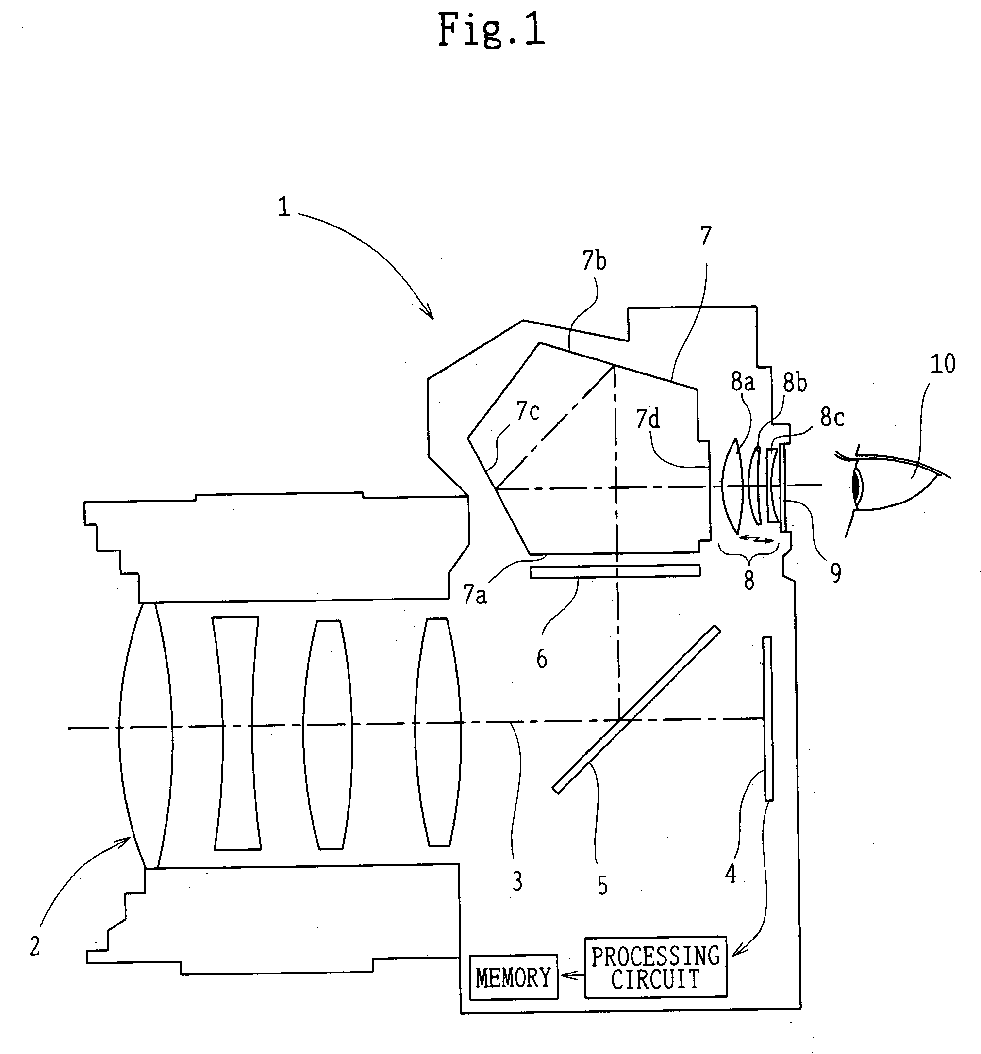
The first embodiment has the pentagonal roof prism 7 and the eyepiece system 8. The eyepiece system 8 includes, in order from the object side, a first lens component 8a with positive refracting power which is a biconvex lens, a second lens component 8b with positive refracting power which is a meniscus lens with a convex surface directed toward the object side, and a third lens component 8c with ...

second embodiment

FIG. 8 shows an optical arrangement, at a diopter of 0 m−1, in the second embodiment of the eyepiece system according to the present invention. For convenience of illustration, a plane-parallel plate-like member in FIG. 8 is shown by developing the pentagonal roof prism.

FIGS. 9A-9D, 10A-10D, and 11A-11D show aberration characteristics in the second embodiment. Also, the diopter (m−1) is taken as the axis of abscissas relative to spherical aberration and curvature of field, and the angle (minute) is taken as the axis of abscissas relative to chromatic aberration of magnification.

The second embodiment has the pentagonal roof prism 7 and the eyepiece system 8. The eyepiece system 8 includes, in order from the object side, the first lens component 8a with positive refracting power which is a biconvex lens, the second lens component 8b with positive refracting power which is a meniscus lens with a convex surface directed toward the object side, and the third lens component 8c with neg...

third embodiment

FIG. 12 shows an optical arrangement, at a diopter of 0 m−1, in the third embodiment of the eyepiece system according to the present invention. For convenience of illustration, a plane-parallel plate-like member in FIG. 12 is shown by developing the pentagonal roof prism.

FIGS. 13A-13D, 14A-14D, and 15A-15D show aberration characteristics in the third embodiment. Also, the diopter (m−1) is taken as the axis of abscissas relative to spherical aberration and curvature of field, and the angle (minute) is taken as the axis of abscissas relative to chromatic aberration of magnification.

The third embodiment has the pentagonal roof prism 7 and the eyepiece system 8. The eyepiece system 8 includes, in order from the object side, the first lens component 8a with positive refracting power which is a biconvex lens, the second lens component 8b with positive refracting power which is a cemented lens of a biconvex lens element 8b1 and a concave meniscus lens element 8b2, with a convex surface ...


PUM


Abstract

A camera includes a screen on which an image of an object is projected, a plurality of reflection surfaces for erecting the image on the screen, and an eyepiece system with positive refracting power for observing the image. In this case, the eyepiece system includes, in order from the object side, a first lens component with positive refracting power, a second lens component with positive refracting power, and a third lens component with negative refracting power. Spacings between the first lens component and the second lens component and between the second lens component and the third lens component are changed to thereby make a diopter adjustment, and the camera satisfies the following conditions:0.15<tan(S)<0.352.00<fb / Y<4.00−0.80<f3 / f<−0.40where S is an angle, at a diopter of 0 m−1, made by the most off-axis chief ray passing through a point on the optical axis at a distance of 23 mm along the optical axis from the exit surface of the third lens component with the optical axis; fb is an air-equivalent length, at a diopter of 0 m−1, from the screen to the entrance surface of the first lens component; Y is a diagonal length of the picture plane on the screen; f3 is the focal length of the third lens component; and f is the focal length, at a diopter of 0 m−1, of the entire system from the screen to the exit surface of the eyepiece system.

Description

BACKGROUND OF THE INVENTION 1. Field of the Invention This invention relates to a camera provided with an eyepiece, and in particular, to a camera having a picture plane of size as small as nearly half of a 135-format film or a silver halide 35-mm film. 2. Description of Related Art In a camera having a picture plane of small size, when a conventional eyepiece is used as it is, an observation image becomes small and an photographer suffers from undue fatigue in using the camera. Thus, in order to enable a large image to be observed through a finder, it is necessary to reduce the focal length of the eyepiece and to increase a finder magnification. Conventional examples in which the focal length of the eyepiece is reduced are disclosed in Japanese Patent Publication Nos. Sho 57-60612 and Hei 7-107581 and Japanese Patent Kokai No. Hei 11-337847. In order to render a finder easy to see, there is the need to ensure a distance from the eyepiece to the pupil position of an observer ...

Claims


Application Information

Patent Timeline
IPC IPC(8): G02B23/14G03B19/12
CPCG03B19/12G02B23/14
Inventor OGATA, YASUZISATORI, TOMOYUKI
Owner OLYMPUS CORP
Why Eureka
Try Eureka