System and method for current-mode amplitude modulation

a current-mode amplitude and modulation technology, applied in the direction of amplifier modification, baseband system details, modulation, etc., can solve the problems of current mirror voltage imbalance, signal clipping/distortion, etc., and achieve linear rf signal amplification, high linear envelope modulation, and efficient operation

Inactive Publication Date: 2005-02-10
ERICSSON INC
View PDF16 Cites 145 Cited by
  • Summary
  • Abstract
  • Description
  • Claims
  • Application Information

AI Technical Summary

Benefits of technology

[0005] The present invention includes a system and method for efficient, linear RF signal amplification. A power amplifier biased for saturated mode operation is powered by a controllable current source. Amplitude modulation of the output signal from the power amplifier is based on controlling its supply current in proportion to an envelope modulation signal. In this manner, the power amplifier may be configured for efficient operation in a saturated mode, while still being used to generate a transmit signal with highly linear envelope modulation. Supply current modulation provides good linearity of control across a broad range of power amplifier operating currents, and may be particularly advantageous for certain types of power amplifier devices, such as heterojunction bipolar transistor (HBT) power amplifiers.

Problems solved by technology

However, the effective DC resistance of the power amplifier can change during operation, leading to voltage imbalances in the current mirror, and potentially leading to signal clipping / distortion.

Method used


Image

  • System and method for current-mode amplitude modulation
  • System and method for current-mode amplitude modulation
  • System and method for current-mode amplitude modulation

Examples


Embodiment Construction

[0029] While the present invention contemplates usage within mobile terminals or other battery-powered RF communication devices where power amplifier efficiency and linearity are critical, it is applicable to a broad range of RF applications. It should further be noted that the present invention is related to the co-pending application entitled, “System and Method of RF Power Amplification,” which is commonly assigned with the instant application. The disclosure of that co-pending application is incorporated herein by reference.

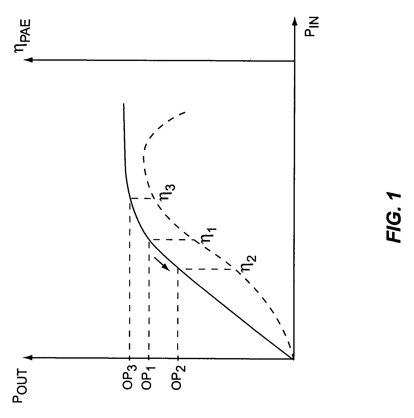
[0030]FIG. 1 depicts a general radio frequency output power curve for a typical power amplifier, and additionally illustrates the general relationship between the amplifier's operating point and its operating efficiency. The horizontal axis represents the RF power of the input signal RFIN, while the left vertical axis represents the RF power of the output signal RFOUT generated by a radio frequency power amplifier, and the right vertical axis represents powe...


PUM


Abstract

An amplifier circuit includes a power amplifier biased for saturated mode operation, and a controllable current source to provide supply current to the power amplifier. The controllable current source effects desired amplitude modulation of the output signal from the power amplifier by modulating the supply current it provides responsive to an amplitude information signal. In one or more embodiments, the current source includes a circuit that is configured to adjust one or more transmitter operating parameters responsive to detecting changes in the effective DC resistance of the power amplifier. For example, the circuit may generate a compensation signal that reduces the effective DC resistance responsive to detecting that the effective DC resistance has undesirably increased. By way of non-limiting examples, such compensation may be effected by changing a current mirror, an amplifier-to-antenna impedance matching, an amplifier bias or device size, or imposing some form of transmit signal back-off.

Description

RELATED APPLICATIONS [0001] The instant application is a continuation-in-part of U.S. patent application Ser. No. 09 / 813,593, which was filed on 21 Mar. 2001, and entitled “System and Method for Current-Mode Amplitude Modulation.” That priority application, which is co-pending and commonly assigned with the instant application, is incorporated herein by reference in its entirety.BACKGROUND OF THE INVENTION [0002] The present invention generally relates to RF power amplifiers and, in particular, relates to efficient, linear RF signal amplification. [0003] Several existing wireless communication standards are either in use, or planned for use in the near future. Current standards that enjoy varying degrees of deployment globally include the TIA / EIA-136 and Global Services for Mobile Communications (GSM) standards, which represent competing approaches for providing wireless communication and data services. The TIA / EIA-136 and GSM standards employ Time Division Multiple Access (TDMA) te...

Claims


Application Information

Patent Timeline
Patent Type & Authority Applications(United States)
IPC IPC(8): H04B1/04H03F3/24
CPCH03C1/06H03C5/00H03F1/02H03F1/0222H03F1/0261H03F1/32H04B2001/0491H03F2200/324H03F2200/456H03F2200/504H04B1/04H04B1/0483H04B2001/045H03F3/24
Inventor PEHLKE, DAVID R.HADJICHRISTOS, ARISTOTELE
Owner ERICSSON INC
Why Eureka
Try Eureka