System and method of RF power amplification

a power amplifier and power amplifier technology, applied in the field of rf power amplifiers, can solve the problems of amplifier power efficiency suffers, mobile terminals usually have significant constraints on overall operating power, etc., and achieve the effect of low minimum resistan

Inactive Publication Date: 2005-01-04
ERICSSON INC
View PDF24 Cites 10 Cited by
  • Summary
  • Abstract
  • Description
  • Claims
  • Application Information

AI Technical Summary

Benefits of technology

The present invention provides a system and method for efficient, linear RF signal amplification. An RF power amplifier circuit configured for efficient, saturated mode operation includes a lossy modulator coupling the voltage supply terminal of the power amplifier to a supply voltage. The lossy modulator varies a series load between the supply voltage and the power amplifier's supply terminal as a function of an amplitude modulation signal. For a given amplifier supply current, the varying load modulates the supply voltage provided to the power amplifier in accordance with the amplitude modulation signal. This load modulation action imparts the desired amplitude modulation to the output signal of the power amplifier, even though the amplifier is configured for saturated mode operation. In this configuration, the power amplifier circuit exhibits both high efficiency and high linearity.
The lossy modulator operates as a variable resistance, responsive to an amplitude modulation signal. The lossy modulator may be realized in both digital an analog form. In operation, the lossy modulator may advantageously provide a variable resistance ranging essentially from zero to infinite resistance. With the ability to operate down to essentially zero resistance, the lossy modulator allows the power amplifier to operate at voltages substantially equal to the supply voltage. The very low minimum on-resistance of the lossy modulator ensures that the maximum dynamic range of the RF output signal is not degraded.

Problems solved by technology

Mobile terminals usually have significant constraints on overall operating power.
However, amplifier power efficiency suffers because of the need for linear amplification.

Method used


Image

  • System and method of RF power amplification
  • System and method of RF power amplification
  • System and method of RF power amplification

Examples


Embodiment Construction

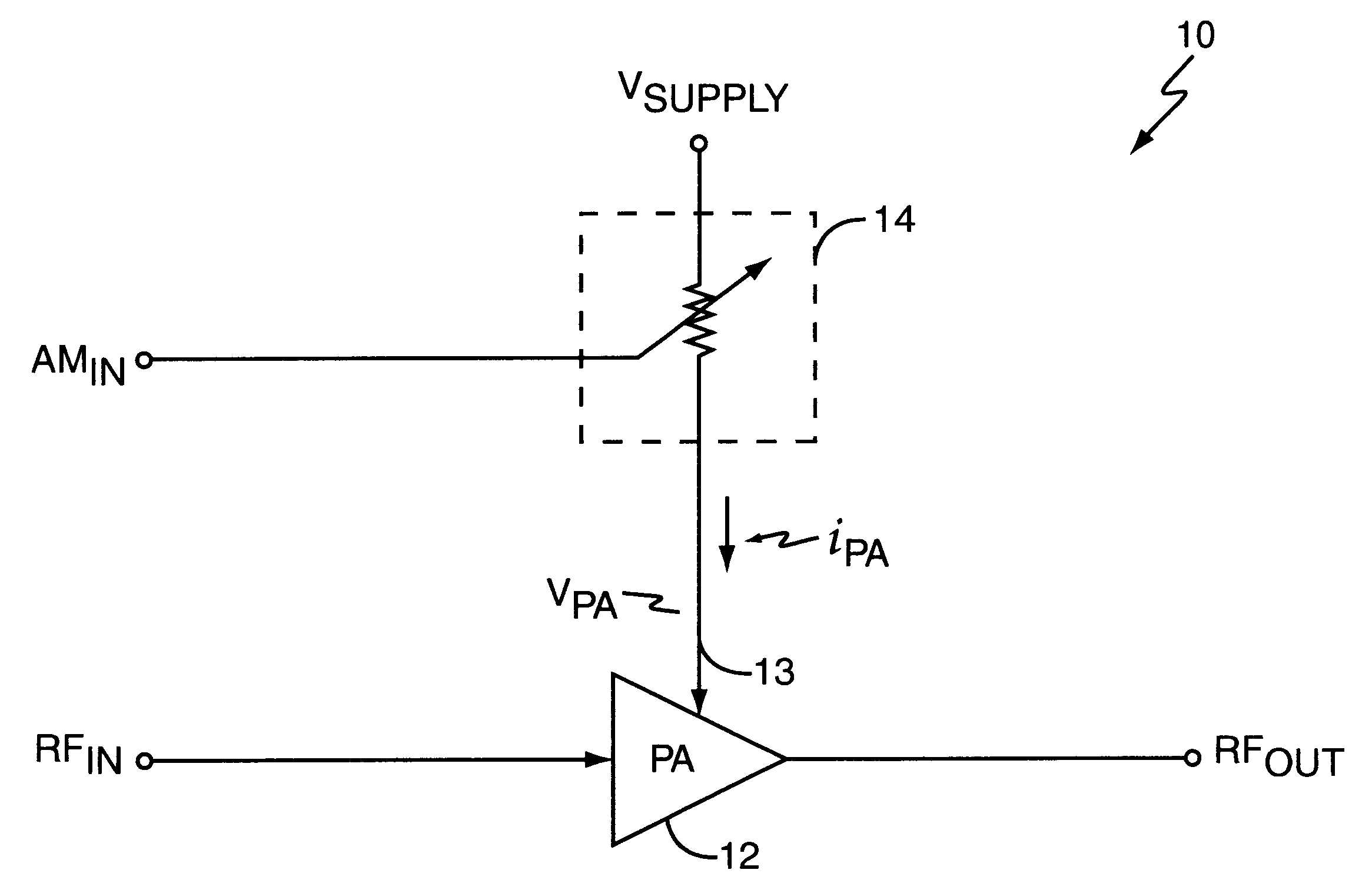
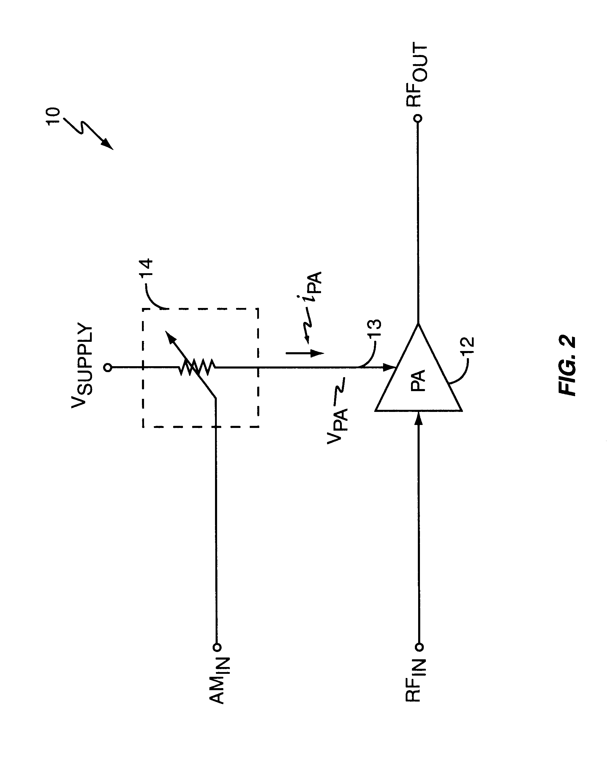
While the present invention contemplates usage within mobile terminals or other battery-powered RF communication devices where power amplifier efficiency and linearity are critical, it is applicable to a broad range of RF applications.

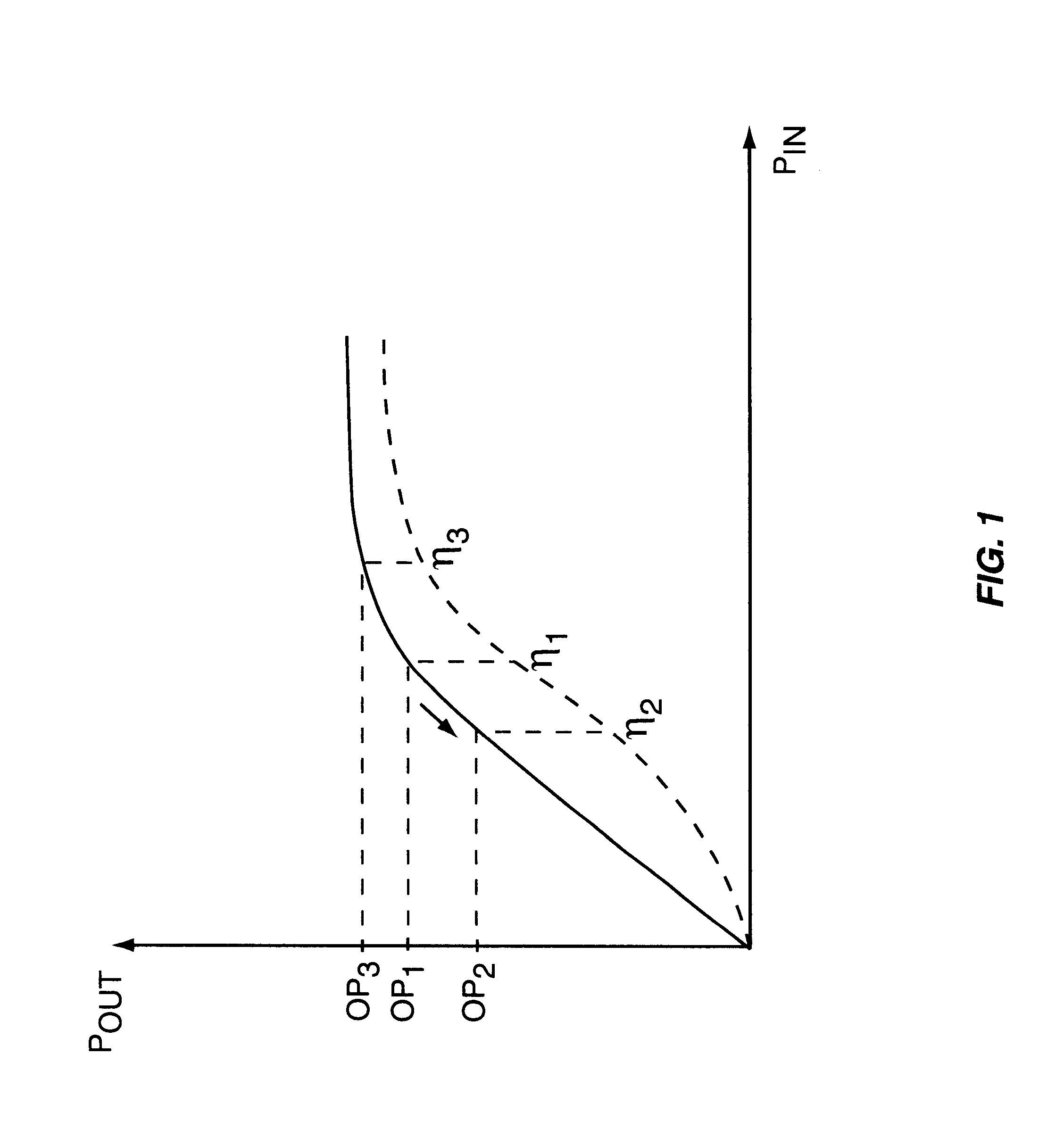
FIG. 1 depicts a general radio frequency output power curve for a typical power amplifier, and additionally illustrates the general relationship between the amplifier's operating point and its operating efficiency. The horizontal axis represents the RF power of the input signal RFIN, while the vertical axis represents the RF power of the output signal RFOUT generated by a radio frequency power amplifier. Operating point 1 (OP1) on the vertical axis illustrates a nominal operating point that might be chosen for linear operation of the power amplifier.

OP1 corresponds to an amplifier operating efficiency η1 in linear mode operation, which may have an exemplary value in the neighborhood of forty percent. The linearity requirements of some modulation standa...


PUM


Abstract

A radio frequency power amplifier circuit provides linear amplitude modulation of a radio frequency output signal while operating in a saturated amplification mode. The power amplifier circuit incorporates a lossy modulator that functions as a variable resistance responsive to an amplitude modulation signal. A supply voltage is coupled to the voltage supply input of the power amplifier circuit through the lossy modulator, such that the supply voltage applied to the power amplifier varies with the amplitude modulation signal. The radio frequency power amplifier circuit modulates the envelope of an RF output signal generated by saturated mode amplification of a constant envelope radio frequency input signal.

Description

BACKGROUND OF THE INVENTIONThe present invention generally relates to RF power amplifiers and, in particular, relates to efficient, linear RF signal amplification.RF signal amplification represents a common step in the generation and transmission of RF signals. Typically, wireless communication devices, such as the mobile terminals used in a wireless communications network, include one or more power amplifiers that provide RF signal amplification. These power amplifiers boost the power level of the RF signal transmitted by the mobile terminals to a level appropriate for transmission to remote base stations and the like.Mobile terminals usually have significant constraints on overall operating power. As the size of mobile terminals decreases in response to consumer demands for convenience and portability, so too does the size of included battery packs. Because the RF power amplification sections of mobile terminals represent a chief area of power consumption, efficient signal amplifi...

Claims


Application Information

Patent Timeline
Patent Type & Authority Patents(United States)
IPC IPC(8): H03F1/02H03F3/60
CPCH03F1/0266H03F3/602H03F2200/504
Inventor PEHLKE, DAVID R.HADJICHRISTOS, ARISTOTLECAMP, JR., WILLIAM O.
Owner ERICSSON INC
Why Eureka
Try Eureka