
Golf ball dimple arrangement method

Active Publication Date: 2005-02-10
BRIDGESTONE SPORTS
View PDF6 Cites 36 Cited by
  • Summary
  • Abstract
  • Description
  • Claims
  • Application Information

AI Technical Summary

Benefits of technology

[0013] Therefore, an object of the present invention is to provide a dimple arrangement method for golf balls so that the ball may have an esthetic outer appearance and excellent aerodynamic symmetry due to the improved symmetry of dimple arrangement, and the expense of golf ball manufacture involving injection molding may be reduced due to the improved point symmetry of dimple arrangement with respect to the golf ball center. Another object is to provide a golf ball manufactured in accordance with the dimple arrangement method.
[0022] The golf ball having dimples arranged according to the method of the invention has the improved symmetry of dimple arrangement which affords high aerodynamic symmetry to the ball in flight.
[0023] When a golf ball is manufactured by injection molding, the injection mold consists of upper and lower mold halves which define a spherical cavity therein and have a parting plane corresponding to the equator of the spherical cavity. The mold is provided near the poles with support pins for holding a core in place within the spherical cavity. The support pins are located at the positions corresponding to those shaded dimples 1s, 2s, 3s and 4s depicted by hatching and designated with suffix “s” in FIGS. 1, 4, 6 and 8. The tip of the support pin also serves to form a dimple at the position with suffix “s” during injection molding. Since the position of a dimple with suffix “s” in FIG. 3 is within the range (angle γ) where the movement of dimples is not necessarily needed, symmetry can be maintained between upper and lower mold halves at the positions where support pins are located, enabling to use common parts for both mold halves. This avoids any increase of the expense required in the implementation of the invention.

Problems solved by technology

This complicates the fabrication of the mold.
However, if no dimples are formed across the equator of the golf ball, the golf ball has an endless land formed along its equator, which means that the spherical polyhedral arrangement is distorted or disordered at this position.
The arrangement of dimples which are juxtaposed in pairs in a strip-like area straddling the equator is often considered unfavorable to an esthetic appearance.
However, arranging dimples with reference longitudes shifted can invite a degradation of the point symmetry of dimple arrangement with respect to the center of the golf ball, that is, a degradation of the symmetry of dimple arrangement, leading to a lowering of flight performance.
Additionally, such a dimple arrangement adds to the manufacturing cost of golf balls for the reason described below.
This negates the share of common parts and needs an accordingly increased expense.

Method used


Image

  • Golf ball dimple arrangement method
  • Golf ball dimple arrangement method
  • Golf ball dimple arrangement method

Examples


first embodiment

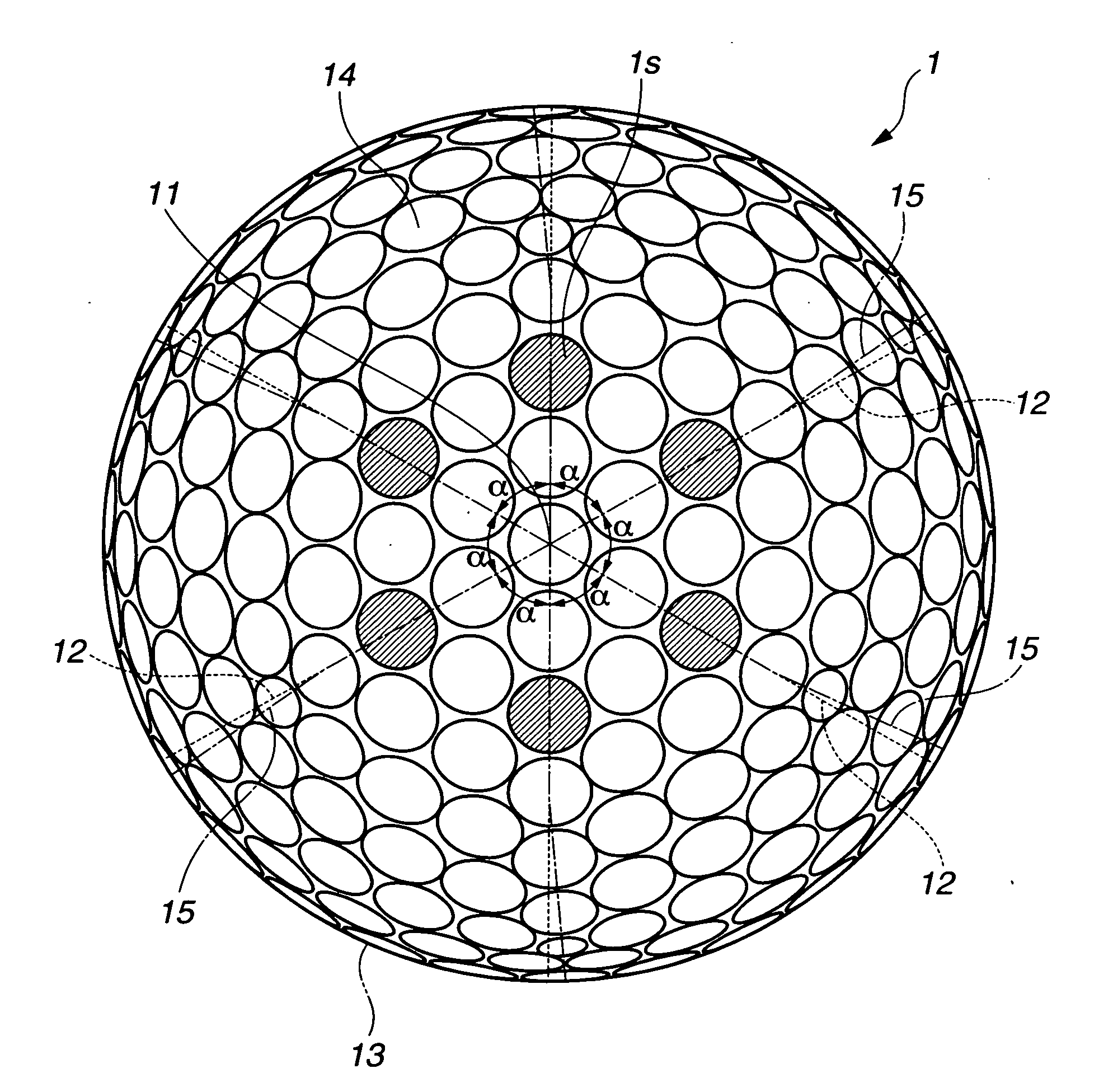
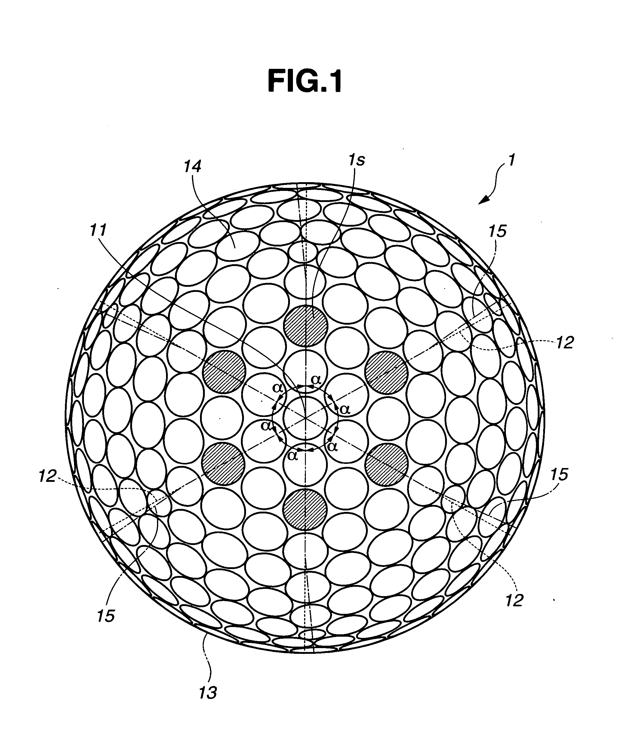
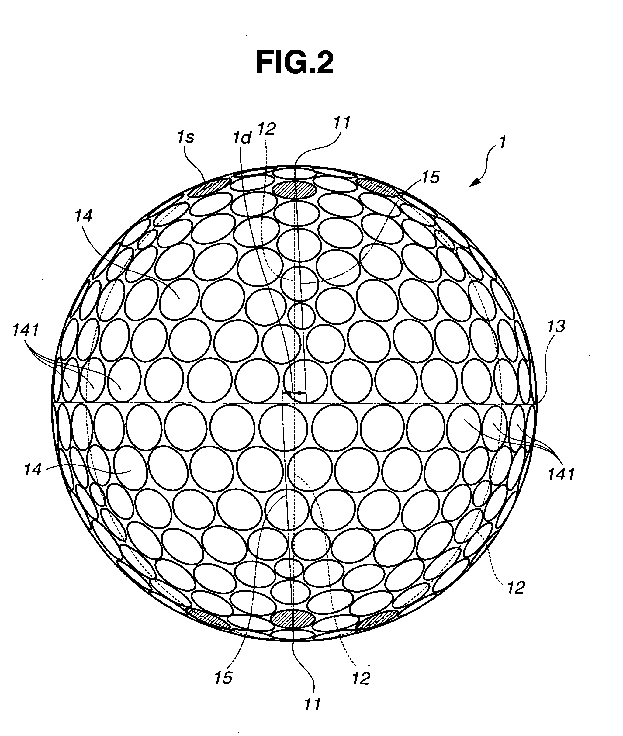
[0034]FIGS. 1 and 2 are plan and elevational views of a golf ball 1 having dimples in the invention, as viewed from above one pole and the equator, respectively. FIG. 3 illustrates a quadrant cross section of the golf ball, taken at the ball center.

[0035] Geometrically described, the golf ball 1 defines a ball center 1c and a spherical surface having a pair of poles 11 and an equator 13, by which the ball is divided into a pair of hemispheres, and an axis passing the poles 11 and the ball center 1c. A plurality of imaginary lines 12 connecting one pole 11 and the equator 13 and extending perpendicular to the equator 13 are drawn on one hemisphere to equally divide the hemispherical surface into a plurality of spherical isosceles triangle regions (in the illustrated embodiment, six lines 12 are drawn to divide the hemispherical surface into six isosceles triangle regions). A number of dimples 14 are arranged within each spherical isosceles triangle region. On the opposed hemisphere w...

second embodiment

[0053]FIGS. 4 and 5 are plan and elevational views of a golf ball 2 having dimples in the invention, as viewed from above one pole and the equator, respectively.

[0054] The golf ball 2 differs from the golf ball 1 of the first embodiment in that the total number of dimples formed on the spherical surface is 330, including 12 dimples with a diameter 4.6 mm and a depth 0.145 mm, 234 dimples with a diameter 4.4 mm and a depth 0.14 mm, 60 dimples with a diameter 3.8 mm and a depth 0.14 mm, 6 dimples with a diameter 3.5 mm and a depth 0.15 mm, 6 dimples with a diameter 3.4 mm and a depth 0.13 mm, and 12 dimples with a diameter 2.6 mm and a depth 0.10 mm. The number of dimples arranged on the first row close to the equator is 30, which is identical with that on the golf ball 1, but among them, four dimples 24 that lie across the equator 23 on each hemisphere are intermittently disposed in the first row of dimples and alternately on the opposite hemispheres and along the equator, providing ...

third embodiment

[0055]FIGS. 6 and 7 are plan and elevational views of a golf ball 3 having dimples in the invention, as viewed from above one pole and the equator, respectively.

[0056] The golf ball 3 differs from the golf ball 1 of the first embodiment in that the total number of dimples formed on the spherical surface is 338, including 234 dimples with a diameter 4.25 mm and a depth 0.14 mm, 12 dimples with a diameter 4.1 mm and a depth 0.16 mm, 80 dimples with a diameter 3.9 mm and a depth 0.14 mm, and 12 dimples with a diameter 2.7 mm and a depth 0.1 mm. The number of dimples arranged on the first row close to the equator is 30, which is identical with that on the golf ball 1, but among them, four dimples 34 that lie across the equator 33 on each hemisphere are intermittently disposed in the first row of dimples and alternately on the opposite hemispheres and along the equator, providing a seamless arrangement. The remaining components are the same as in the golf ball 1.


PUM


Abstract

A method for arranging dimples on a golf ball involves the steps of previously drawing a plurality of imaginary lines connecting one pole and the equator on one hemisphere to equally divide the hemispherical surface into a plurality of spherical isosceles triangle regions; arranging a number of dimples within a pair of spherical isosceles triangle regions such that the dimples in the triangle regions are in axial symmetry with respect to the imaginary line; rotationally moving the arranged dimples about the ball axis; and arranging dimples on the other hemisphere such that they are in point symmetry with the dimples as moved on the one hemisphere with respect to the ball center.

Description

CROSS-REFERENCE TO RELATED APPLICATION [0001] This non-provisional application claims priority under 35 U.S.C. section 119(a) on Patent Application No. 2003-289840 filed in Japan on Aug. 8, 2003, the entire contents of which are incorporated herein by reference. TECHNICAL FIELD [0002] This invention relates to a golf ball having improved aerodynamic symmetry and a method for arranging dimples on a golf ball. BACKGROUND ART [0003] A plurality of dimples are arranged on the surface of a golf ball for the purpose of reducing the air resistance of the ball in flight. From the standpoint of further improving the aerodynamic symmetry so that the ball may exert consistent flight performance independent of the point of impact, it is desirable to arrange the dimples on the golf ball surface as uniformly as possible. [0004] Known approaches for the uniform arrangement of dimples on the golf ball surface include the use of spherical polyhedral arrangement patterns such as spherical icosahedral...

Claims


Application Information

Patent Timeline
IPC IPC(8): A63B37/00A63B37/12
CPCA63B37/0004A63B45/00A63B37/0006A63B37/00065
Inventor KASASHIMA, ATSUKISATO, KATSUNORI
Owner BRIDGESTONE SPORTS
Learn More