Image processing/displaying apparatus and method of controlling the same

a technology of image processing and displaying apparatus, which is applied in the field of image processing/displaying apparatus for medical use, can solve the problems of not having not being able to provide a good user interface, and not being able to display 3-dimensional images in a way that is convenient and convenient to determine, and achieves easy and correct identification, and easy and correct identification

Active Publication Date: 2005-02-10
TOSHIBA MEDICAL SYST CORP
View PDF3 Cites 111 Cited by
  • Summary
  • Abstract
  • Description
  • Claims
  • Application Information

AI Technical Summary

Benefits of technology

[0017] In view of the above, it is an object of the present invention to provide an image processing / displaying apparatus and a method of controlling the same, capable of easily and correctly determining whether there is an obstacle on or close to a paracentesis needle insertion path from an needle insertion point to an affected part to be treated.
[0018] It is another object of the present invention to provide an image processing / displaying apparatus and a method of controlling the same, capable of displaying a paracentesis needle insertion point in an easy-to-recognize manner.
[0019] It is another object of the present invention to provide an image processing / displaying apparatus and a method of controlling the same, capable of easily and correctly identifying even a tumor or tumors that would be difficult to identify using an ultrasonic imaging apparatus, during treatment or at a time immediately before starting treatment, based on information obtained in planning of the treatment.

Problems solved by technology

However, 3-dimensional imaging tools are not widely used in planning or treatment of paracentesis or in aftercare.
However, as a tool of assisting paracentesis treatment or removal of a tissue (for a biopsy), the manner of displaying 3-dimensional images is not good enough, and a good enough user interface is not available.
Ultrasonic imaging does not allow simultaneous observation of the whole of liver and adjacent parts such as a diaphragm.
This makes it impractical to use an X-ray CT scanner or the like to determine a needle insertion point in a 3-dimensional image at a time immediately before starting treatment.
However, it is still difficult to correctly determine whether there is an obstacle on or close to a path along which to insert a needle.
Even when a needle insertion position has been determined, the determined needle insertion position on the body surface is not displayed in an easy-to-recognize manner.
However, there is still a problem that a part to be treated is displayed only on an X-ray CT image and not displayed on an ultrasonic diagnostic apparatus.
Even when an ultrasonic diagnostic apparatus is capable of displaying an image of a part to be treated, the image is not clear enough.
Another still existing problem is that when there are two or more parts to be treated, it is difficult to perform treatment based on only images obtained in planning of treatment.
In addition, there is another problem that it is difficult to make comparison after treatment among images acquired by different kind modality each other.

Method used


Image

  • Image processing/displaying apparatus and method of controlling the same
  • Image processing/displaying apparatus and method of controlling the same
  • Image processing/displaying apparatus and method of controlling the same

Examples


first embodiment

[0081] First Embodiment

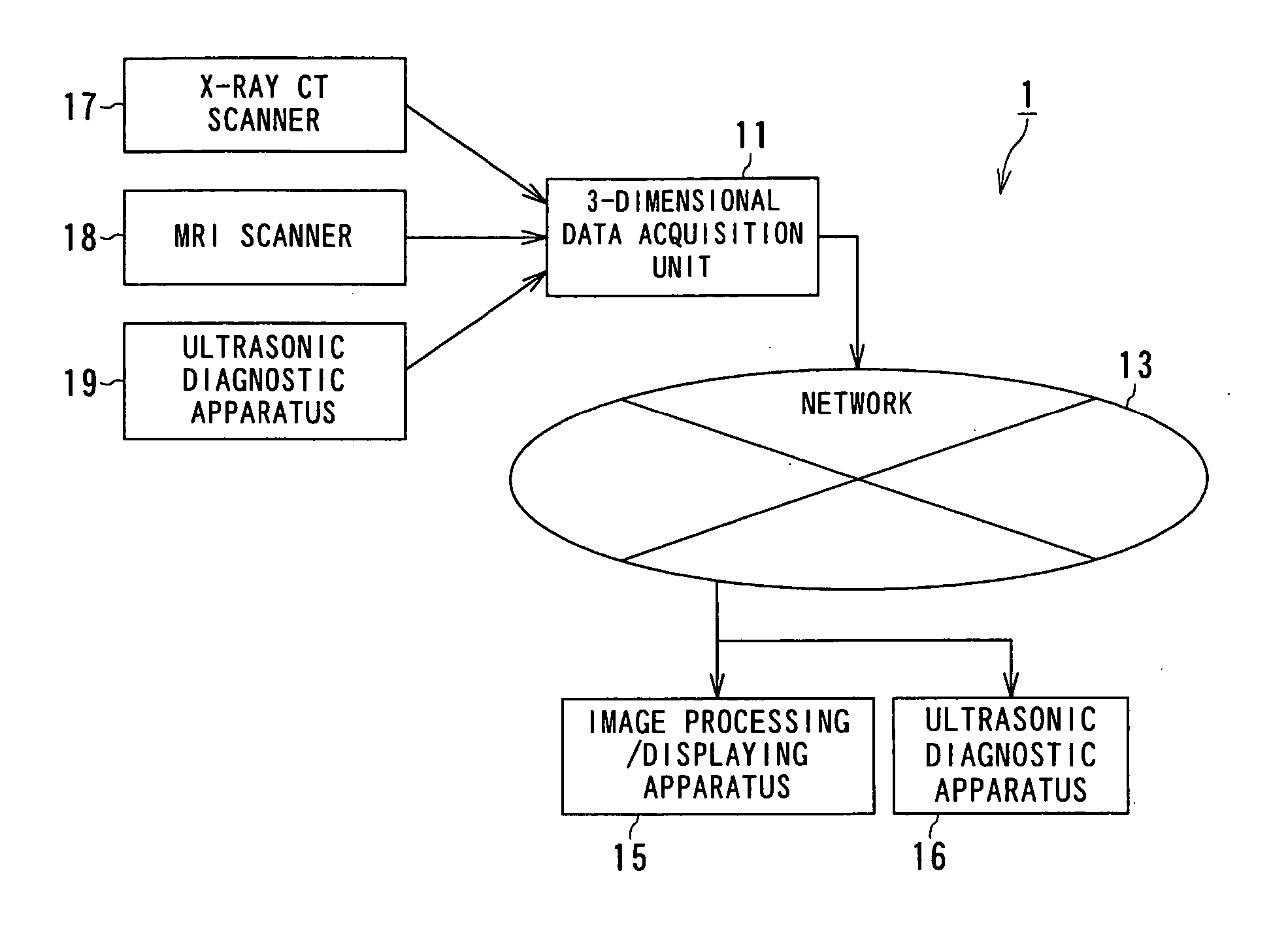
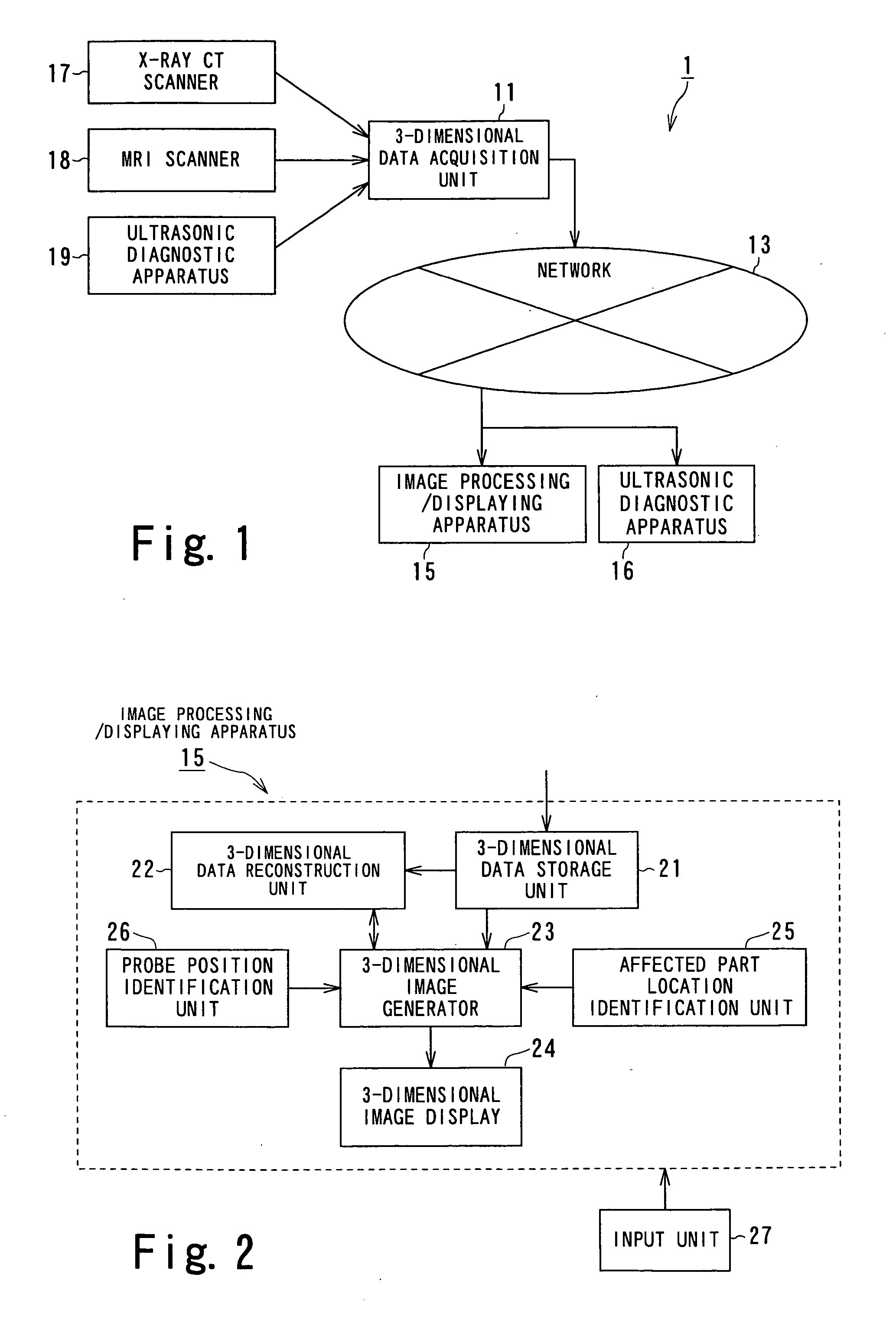
[0082] An image processing / displaying apparatus according to a first embodiment of the present invention is described below with reference to the accompanying drawings. FIG. 1 is a diagram showing an overall structure of a diagnostic system 1 including an image processing / displaying apparatus for medical use according to the first embodiment of the present invention. The diagnostic system 1 includes a 3-dimensional data acquisition unit 11 for acquiring 3-dimensional data, a network 13 such as a local area network (LAN) disposed in a hospital for transmitting the 3-dimensional volume data acquired by the 3-dimensional data acquisition unit 11, a image processing / displaying apparatus 15 for receiving the 3-dimensional data transmitted via the network 13, processing the received 3-dimensional data as will be described later, and displaying the resultant 3-dimensional data, and an ultrasonic diagnostic apparatus 16 for displaying a real-time image of a paracentes...

modification 1

[0119] Modification 1

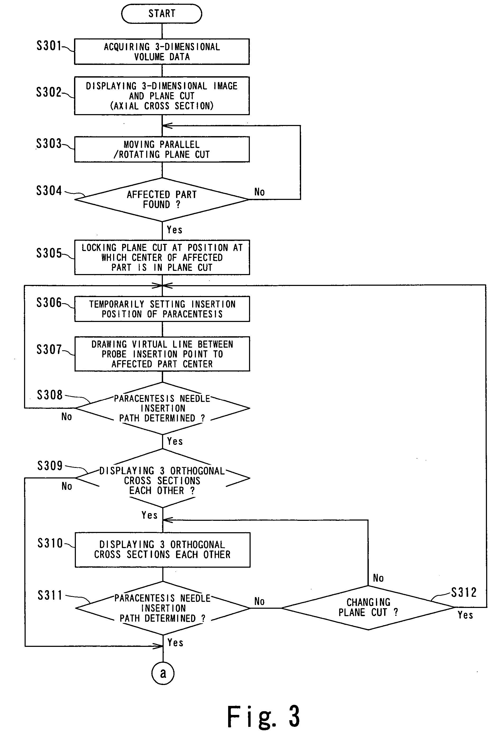
[0120] In stead of a single virtual paracentesis ultrasonic cross section 66 in the above-described manner, virtual paracentesis ultrasonic cross sections 66 corresponding to plane cuts 43 in different positions corresponding to spaces between costas or a point below costal arch may be simultaneously displayed as shown in FIG. 7. That is, as shown in FIG. 7A, when plane cuts 43, 43A and 43B are set by a user such that each plane cut passes through the affected part center 45 and such that respective plane cuts pass through different spaces between costa or a point below a costal arch (corresponding to probe lines), virtual paracentesis ultrasonic cross sections 66, 66A, and 66B corresponding to the respective plane cuts 43, 43A, and 43B are displayed side by side on the screen as shown in FIG. 7B. The user selects a proper one of the virtual paracentesis ultrasonic cross sections 66, 66A, and 66B and sets the paracentesis needle insertion path.

modification 2

[0121] Modification 2

[0122] The location of liver varies depending on the breathing phase because the location of a diaphragm varies depending on the breathing phase. More specifically, in abdominal respiration, the diaphragm moves downward in an inspriatory phase and upward in an expiratory phase. Therefore, the location of liver relative to costas in an X-ray CT image taken in a state in which breathing is stopped in the inspiratory phase can be different from the location of liver in a state in which paracentesis treatment is performed using an ultrasonic diagnostic apparatus, because paracentesis treatment is not necessarily performed in the inspirtory phase. For example, the location of the ultrasonic cross section relative to a particular space between costas varies in the range of −1 cm to +1 cm approximately.

[0123] In view of the above fact, as shown in FIG. 8, in addition to an initial plane cut 43 and a virtual ultrasonic cross section 66 corresponding thereto, a pluralit...


PUM


Abstract

An image processing / displaying apparatus comprises a data storage unit configured to store 3-dimensional volume data, a cross section information generation unit configured to generate cross section information by reconstructing the 3-dimensional volume data stored in the data storage unit, an image display unit configured to display a cross section image of a subject in accordance with the cross section information generated by the cross section information generation unit, a locking unit configured to designate an affected part in the cross section image as a rotation center and a control unit configured to control image rotation on the image display unit so that the affected part is contained in the cross section image, when operation for rotating cross section is performed by an operator.

Description

BACKGROUND OF THE INVENTION [0001] 1. Field of the Invention [0002] The present invention relates to an image processing / displaying apparatus for medical use, and more particularly, to an image processing / displaying apparatus for assisting planning of paracentesis and assisting actual paracentesis in which a paracentesis needle is inserted into a subject to remove a tissue of an affected part or treat the affected part. The present invention also relates to a method of controlling such an image processing / displaying apparatus. [0003] 2. Description of the Related Art [0004] Cancer is one of three major diseases in Japan. Of those three major diseases, only cancer is increasing in mortality. Of all types of cancer, 10% is cancer of liver and the percentage thereof is increasing. Early detection of cancer of liver has become possible as a result of advance in medical modality technology, in particular, 3-dimensional imaging technology using an ultrasonic diagnostic apparatus, an MRI s...

Claims


Application Information

Patent Timeline
Patent Type & Authority Applications(United States)
IPC IPC(8): A61B6/12A61B19/00
CPCA61B6/12A61B19/20A61B19/52A61B2019/5289A61B2019/5238A61B2019/5276A61B2019/5236A61B90/10A61B90/36A61B2090/364A61B2090/374A61B2090/376A61B2090/378
Inventor YAMAGATA, HITOSHIMINE, YOSHITAKEKAMIYAMA, NAOHISAHIKI, SUSUMUTANAKA, YUKOTANAKA, MASAAKI
Owner TOSHIBA MEDICAL SYST CORP
Why Eureka
Try Eureka