
Open hole tractor with tracks

a technology of open-hole tractor and track, which is applied in the direction of borehole/well accessories, drilling pipes, drilling rods, etc., can solve the problems of prior downhole tractors deficient in the ability to develop the force required to convey tools, and holes with varying diameters and irregular bore profiles

Active Publication Date: 2005-02-17
SCHLUMBERGER TECH CORP
View PDF12 Cites 72 Cited by
  • Summary
  • Abstract
  • Description
  • Claims
  • Application Information

AI Technical Summary

Benefits of technology

The present invention is a downhole tractor that includes a track assembly, a motor, and a lower and upper arm. The track assembly includes idler wheels and a continuous track rotatably disposed around the idler wheels. The motor is connected to the track assembly to rotate it. The lower arm is pivotally connected to the tractor housing and the track assembly. The upper arm is pivotally connected to the tractor housing. The invention also includes a link assembly connected to the motor and the track assembly, a hydraulic system, a second motor, and a slider assembly. The invention allows for the track assembly to move between open and closed positions and can be used in drilling oil wells.

Problems solved by technology

The prior downhole tractors are deficient in a variety of respects, including in the areas of operating in open holes wherein the tractor may be required to traverse a variety of soil / formation consistencies (e.g., soft, firm, rigid, etc.), and in bore holes having varying diameters and non-uniform and irregular bore profiles.
Also, the prior tractors are deficient in their ability to develop the forces required to convey the tools used in open holes for formation evaluation, which are usually much heavier than the tools used in cased holes for production logging.
Another area in which prior tractors are deficient is in their ability to operate while submerged in drilling fluids at high temperatures well above 150 degrees C.; this is due in part to the poor efficiency of such prior tractors in dissipating heat.

Method used


Image

  • Open hole tractor with tracks
  • Open hole tractor with tracks
  • Open hole tractor with tracks

Examples


Embodiment Construction

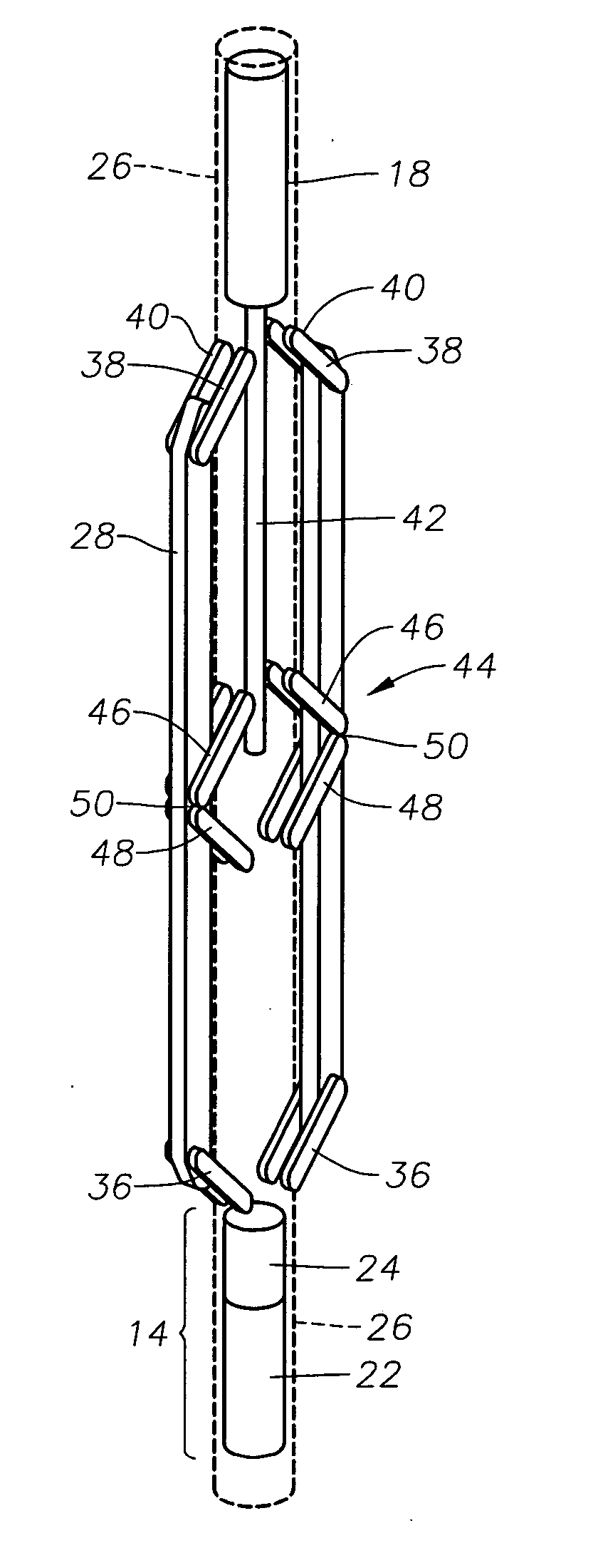
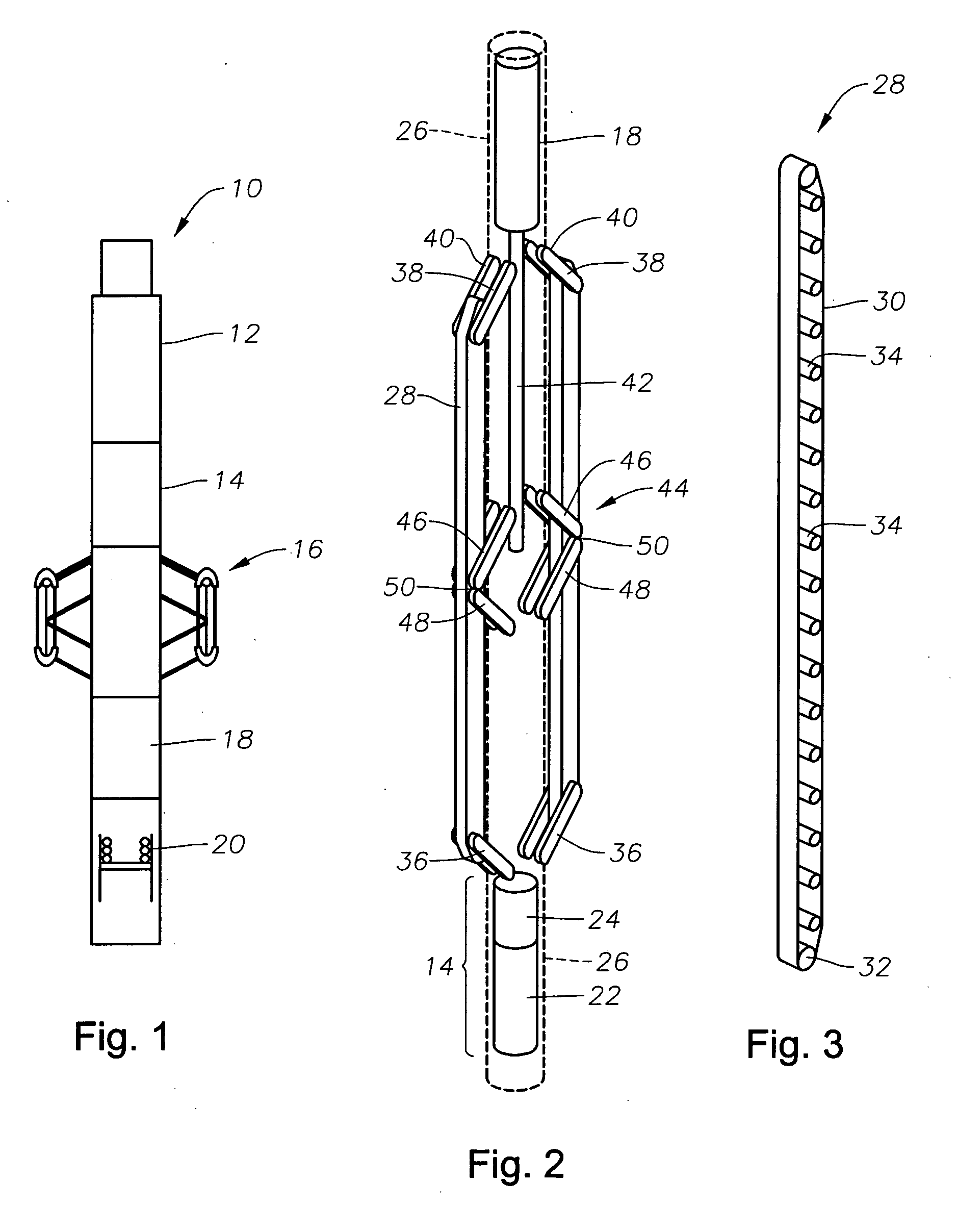
[0043] Referring to the drawings in detail, wherein like numerals denote identical elements throughout the several views, there is shown in FIG. 1 a specific embodiment of an open hole tractor 10 constructed in accordance with the present invention that may include five main sections: (1) an electronics section 12; (2) a drive section 14; (3) a track section 16; (4) an open / close system 18 for opening and closing the track section; and (5) a compensation system 20 for providing the internal pressure required to compensate the system against downhole pressure. A more detailed illustration of a specific embodiment of the present invention is shown in FIG. 2, wherein the drive section 14 may include a motor 22 and a gear box 24 connected in series and enclosed within a tractor housing 26. The motor 22 and gear box 24 are preferably submerged in oil which is maintained at a proper pressure by the compensation system 20. The output of the gear box 24 is used to drive one or more track as...


PUM


Abstract

A downhole tractor is provided that may be used in open or cased wells, and is also designed for use in open holes having a variety of soil / formation consistencies (e.g., soft, firm, rigid, etc.), varying diameters and non-uniform and irregular bore profiles. The tractor may include a track assembly including a plurality of idler wheels and a continuous track rotatably disposed around the idler wheels. A motor may be adapted to rotate the track around the idler wheels. Upper and lower arms may be pivotally connected to opposite ends of the track assembly and pivotally connected to a tractor housing. An actuator arm or link assembly may be provided to impart an outward force to the track assembly to move the track assembly outwardly into an open position and a retracting force to retract the track assembly into a closed position. A rotatable screw may be connected to a second motor, or a rod may be connected to a hydraulic system, to actuate the actuator arm or link assembly.

Description

CROSS-REFERENCE TO RELATED APPLICATIONS [0001] This application claims priority from U.S. Provisional Application No. 60 / 487,699, filed Jul. 16, 2003, which is incorporated herein by reference.BACKGROUND OF THE INVENTION [0002] 1. Field Of The Invention [0003] The present invention generally pertains to apparatus, systems and methods for conveying equipment in a well, and more particularly to a downhole tractor that may be used in both open and cased wells and that is adaptable when used in open holes to all types of soil conditions and formation consistencies, whether they be soft, firm, or otherwise. [0004] 2. Description Of The Related Art [0005] It is known within the oil and gas industry to use a downhole tractor to convey equipment, such as logging equipment, within a well, and that the use of a downhole tractor is often especially useful when it is desired to convey equipment in highly-deviated and horizontal well bores. Examples of downhole tractors can be found in U.S. Pat....

Claims


Application Information

Patent Timeline
Patent Type & Authority Applications(United States)
IPC IPC(8): E21B23/00E21B23/14
CPCE21B2023/008E21B23/14E21B23/001
Inventor GUERRERO, JULIO C.DOERING, FALK W.ROY, CARL J.BEGUIN, PAUL J.
Owner SCHLUMBERGER TECH CORP
Learn More