Multi-band printed dipole antenna

a dipole antenna and multi-band technology, applied in the direction of individual energised antenna arrays, resonant antennas, radiating elements structural forms, etc., can solve the problem that the use of one dipole in one frequency band is not adapted for ultra-fast broadband operation without other components

Inactive Publication Date: 2005-02-17
HON HAI PRECISION IND CO LTD
View PDF10 Cites 108 Cited by
  • Summary
  • Abstract
  • Description
  • Claims
  • Application Information

AI Technical Summary

Benefits of technology

[0007] A multi-band antenna for an electronic device comprises a dielectric substrate, a pair of substantially U-shaped dipole elements disposed on a top surface of the substrate, a pair of dipole elements each connecting with one of the pair of U-shaped dipole elements, a capacitor and a feeder cable comprising an outer shield conductor coupling wi

Problems solved by technology

However, using one dipole in one frequency band is not adapt

Method used


Image

  • Multi-band printed dipole antenna
  • Multi-band printed dipole antenna
  • Multi-band printed dipole antenna

Examples


Embodiment Construction

[0019] Reference will now be made in detail to a preferred embodiment of the present invention.

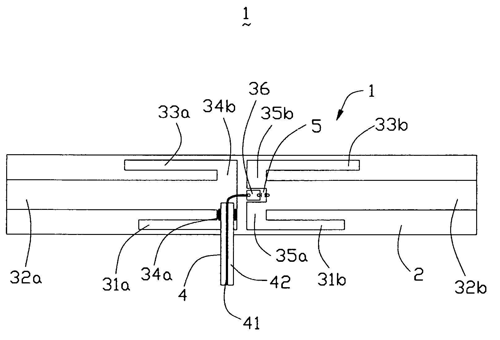
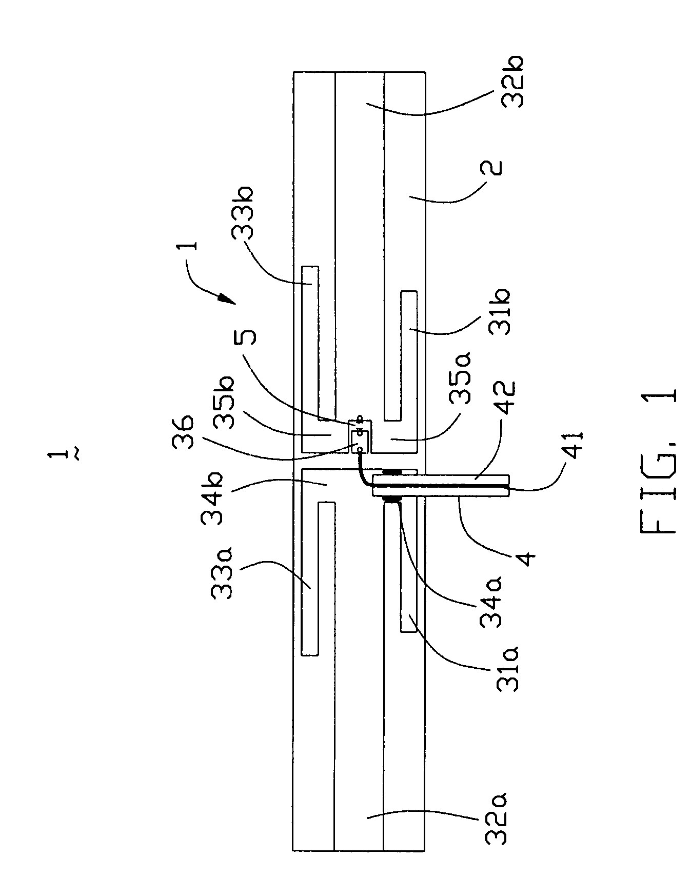
[0020] Referring to FIG. 1, a multi-band printed dipole antenna 1 in accordance with the present invention for an electronic device, such as a WLAN Card (Wireless Local Area Network Card), comprises an elongate insulative substrate 2, a first pair of dipole elements 31a, 31b, a second pair of dipole elements 32a, 32b, a third pair of dipole elements 33c, 33d, a first and a second pairs of connecting elements 34a, 34b, 35a, 35b, a connecting tab 36 and a capacitor 5.

[0021] Each pair of dipole elements are printed traces and aligned in a longitudinal direction of the substrate 2. The three pairs of dipole elements 31a, 31b, 32a, 32b, 33a, 33b are parallel to each other with a predetermined distance therebetween. The first pair of dipole elements 31a, 31b are the shortest ones while the second ones 32a, 32b are the longest and widest. The third pair of dipole elements 33a, 33b are little lo...


PUM


Abstract

A multi-band printed dipole antenna (1) for an electronic device includes an elongate insulative substrate (2), a first, second and third pairs of dipole elements (31a, 31b, 32a, 32b, 33a, 33b) closely and parallelly disposed on the substrate, a capacitor (5) and a feeder cable (4). The first, second and third pair of dipole elements respectively couple with the feeder cable to form a first, second and third dipole antennas. The capacitor is used to improve the impedance matching of the second dipole antenna.

Description

BACKGROUND OF THE INVENTION [0001] 1. Field of the Invention [0002] The present invention relates to an antenna, and in particular to a multi-band printed dipole antenna employed in a mobile electronic device. [0003] 2. Description of the Prior Art [0004] Dipole antennas are widely used in many kinds of communication devices. Some inventions about dipole antennas, especially printed dipole antennas have been introduced to achieve multi-band use. For instance, U.S. Pat. No. 4,205,317 discloses a tri-band dipole antenna in radio or TV devices. The tri-band antenna comprises a pair of closely spaced parallel central conductors. The tri-band antenna also comprises three pairs of dipole elements disposed in a symmetrical array and extending outwardly from the central conductors. The three pairs dipole elements are in different lengths and respectively cover three different frequency bands. However, using one dipole in one frequency band is not adapted for an ultra broadband operation wit...

Claims


Application Information

Patent Timeline
IPC IPC(8): H01QH01Q1/38H01Q5/00H01Q5/371H01Q9/16H01Q9/28H01Q9/44H01Q21/12H01Q21/30
CPCH01Q1/38H01Q5/371H01Q21/30H01Q9/285
Inventor YANG, FANHE, ZIMINGPENG, PINGQIAN, YIN
Owner HON HAI PRECISION IND CO LTD
Why Eureka
Try Eureka