

Inkjet head printing device
a printing device and inkjet head technology, applied in printing, inking apparatus, other printing apparatus, etc., can solve the problems of inability to explain the control of the inkjet head, the amount of ink ejection is improperly increased or decreased relative, and the quality of the image is deteriorated
- Summary
- Abstract
- Description
- Claims
- Application Information
AI Technical Summary
Benefits of technology
Problems solved by technology
Method used
Image

Examples
first embodiment
[0063] First Embodiment
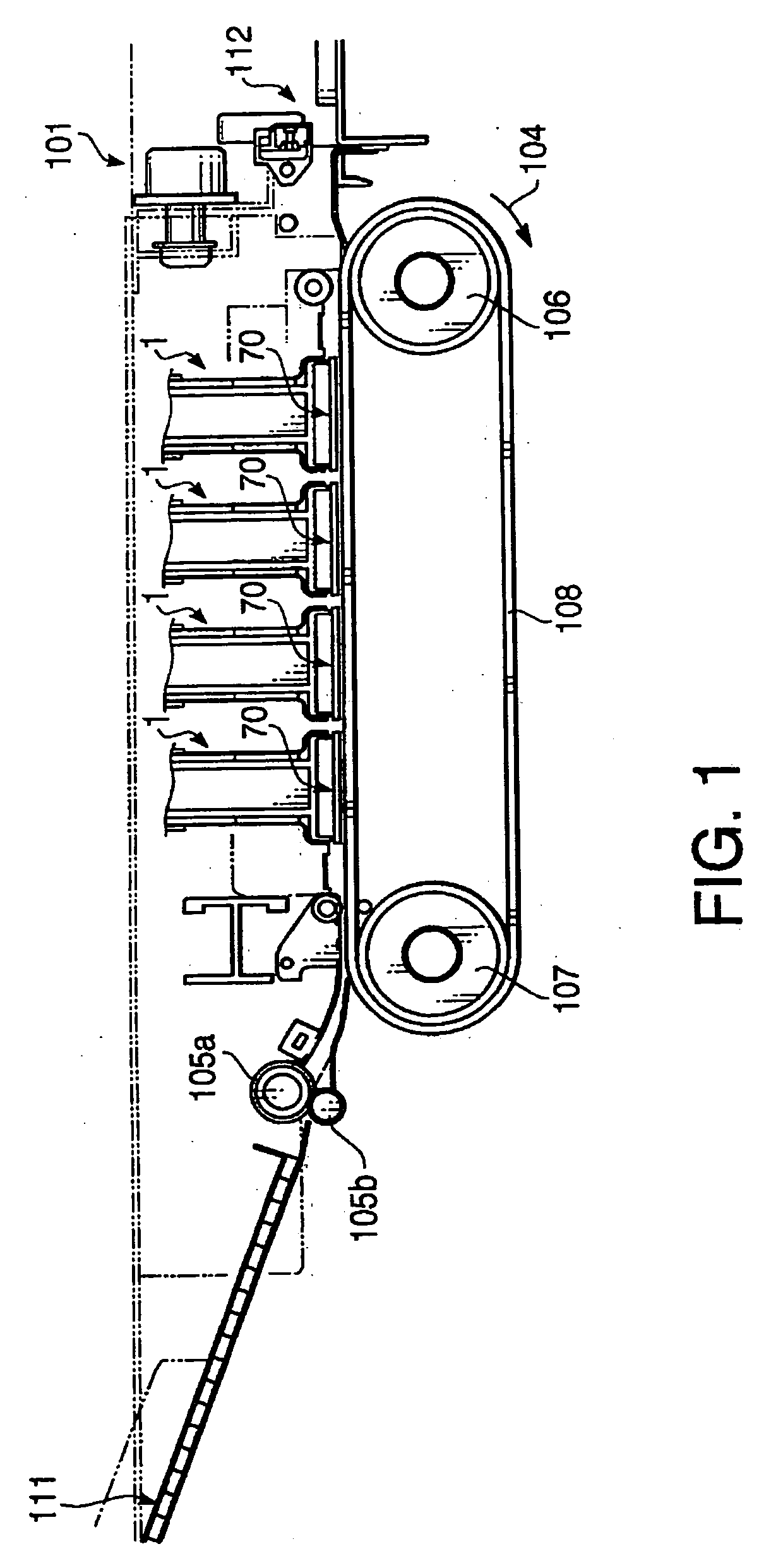
[0064]FIG. 1 schematically shows an inkjet printer 101 according to a first embodiment of the invention. As shown in FIG. 1, the inkjet printer 101 has four inkjet heads 1 for forming color images. In the inkjet printer 101, a sheet feeding unit 111 is located on an upstream side of a sheet feed path, and a sheet ejecting portion 112 is located on a downstream side of the sheet feed path. As described in detail below, the inkjet printer 101 has a control unit 113 which controls operation of the inkjet heads 1.
[0065] As shown in FIG. 1, along the sheet feed path, a pair of sheet feed rollers 105a and 105b is located immediately on the downstream side of the sheet feeding unit 111. By the pair of sheet feed rollers 105a and 105b, the sheet is fed from the sheet feeding unit 111 into the inside of the inkjet printer 101.
[0066] At a midway of the sheet feed path, a carrying belt 108 which is driven by belt rollers 106 and 107 is located. An outer surface of the ...
second embodiment
[0149] Second Embodiment
[0150] Hereafter, an inkjet printer according to a second embodiment of the invention will be described. The feature of the inkjet printer according to the second embodiment is that only the function of a pulse generator 200A is different from that of the pulse generator 200 of the first embodiment. Therefore, to elements which are similar to those of the first embodiment, same reference numbers are assigned, and explanations thereof will not be repeated.
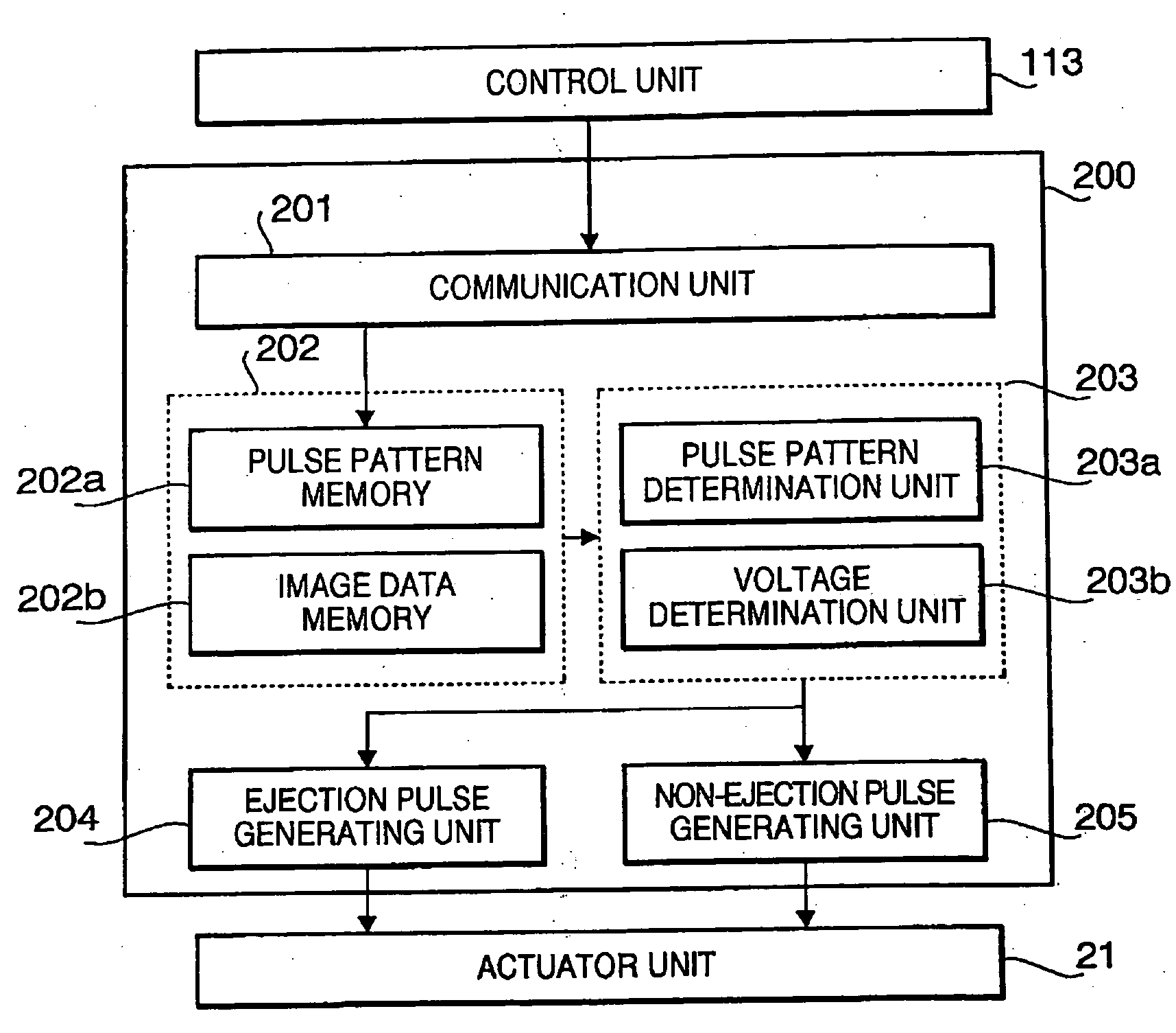
[0151]FIG. 13 shows a block diagram of the pulse generator 200A which is constituted of the CPU, ROM storing the programs and RAM mounted on the printed circuit board 81, and the driver IC 80. As shown in FIG. 13, the same functional units, i.e., the communication unit 201, the memory 202, the ejection pulse generating unit 204, and the non-ejection pulse generating unit 205, which are used in the pulse generator 200 of the first embodiment, are also used in the pulse generator 200A. Therefore, the explanati...
third embodiment
[0167] Third Embodiment
[0168] Hereafter, an inkjet printer according to a third embodiment of the Invention will be described. The feature of the inkjet printer according to the third embodiment is that only the function of a pulse generator 200B is different from that of the pulse generator 200 of the first embodiment. Therefore, to elements which are similar to those of the first embodiment, same reference numbers are assigned, and explanations thereof will not be repeated.
[0169]FIG. 15 shows a block diagram of the pulse generator 200B which Is constituted of the CPU, ROM storing the programs and RAM mounted on the printed circuit board 81, and the driver IC 80. As shown in FIG. 15. the pulse generator 200B includes the communication unit 201, the memory 202, an ejection pulse generating unit 204B and a non-ejection pulse generating unit 205B. and a pulse supplying unit 206. Since the communication unit 201 and the memory 202 are the same as those of the first embodiment, the exp...
PUM
 Abstract
Description
Claims
Application Information