Droplet dispensing system

a droplet and liquid technology, applied in the field of liquid dispensing systems, can solve the problems of difficult control of the precise volume of dispensed sample using capillary tubes, low injection efficiency inherent in capillary tubes, contamination of capillary tubes, etc., and achieve the effects of enhancing liquid sample application, efficient and rapid dispensing, and fast and flexibl

Inactive Publication Date: 2005-02-17
CYTONOME INC
View PDF18 Cites 66 Cited by
  • Summary
  • Abstract
  • Description
  • Claims
  • Application Information

AI Technical Summary

Benefits of technology

[0009] The droplet dispensing system provides fast and flexible filling of a predetermined amount of liquid sample in the dispensing system via the tip of a dispensing pin. The droplet dispensing system provides efficient and rapid dispensing of the liquid sample from the tip of a dispensing pin in the form of droplets having a precisely controlled volume. The droplet dispensing system enhances liquid sample application by improving efficiency, speed and controllability, while reducing waste and contamination.

Problems solved by technology

A significant drawback of using a capillary tube concerns the low injection efficiency inherent to capillary tubes, that is, the ratio between the volume of liquid required for a particular chemical operation in a part of the microfluidic system, and the total volume of liquid required for the introductory operation.
Moreover, it is generally difficult to control the precise volume of dispensed sample using capillary tubes.
Furthermore, capillary tubes are subject to contamination, because the same port used to fill the tube is also used to eject the liquid sample.
A drawback of the pin-based system described in the '946 patent concerns the ability to control the amount of delivered sample.
The pin-based system is subject to contamination and breakage, because it requires direct contact between the pin tip and the printing substrate.
Another drawback concerns the difficulty of precisely positioning the tip of the pin to provide sufficient contact to result in delivery of a sample.
Furthermore, it is difficult to control the amount of sample that is acquired and dispensed from the capillary dispenser of the '246 patent.

Method used


Image

  • Droplet dispensing system
  • Droplet dispensing system
  • Droplet dispensing system

Examples


Embodiment Construction

[0019] The present invention provides a droplet dispensing system for forming and dispensing liquid droplets of a sample for fluidic systems. The droplet dispensing system of the present invention provides precise sample uptake and delivery of a liquid sample to a sample handling system in the form of sub-micron-sized droplets. The droplet dispensing system is suitable for use in a basic research or a commercial environment. The droplet dispensing system significantly improves sample introduction into a sample handling system by increasing the efficiency, speed and controllability of forming and dispensing droplets while significantly reducing waste and contamination. Those skilled in the art will appreciate that the present invention may be implemented in a number of different applications and embodiments and is not specifically limited in its application to the particular embodiment depicted herein.

[0020] The droplet dispensing system of the present invention provides significant...


PUM

PropertyMeasurementUnit
diameteraaaaaaaaaa
diameteraaaaaaaaaa
diameteraaaaaaaaaa

Abstract

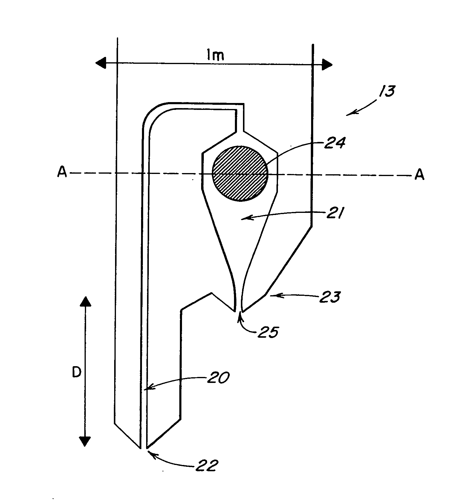
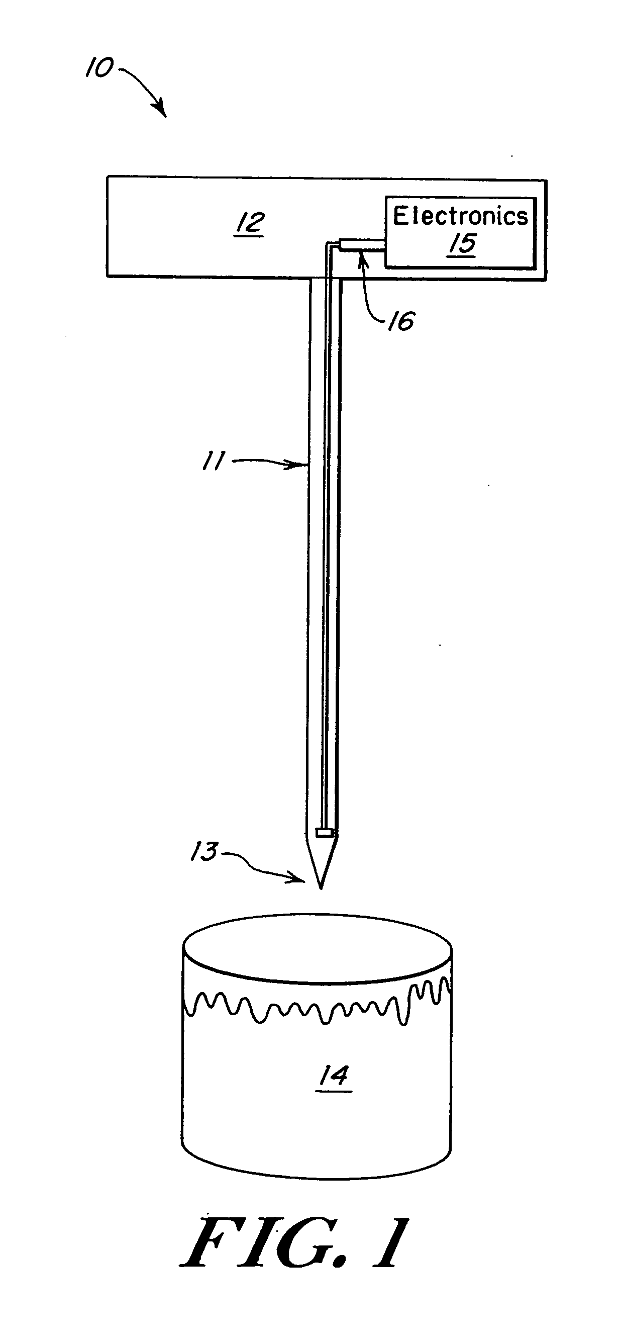
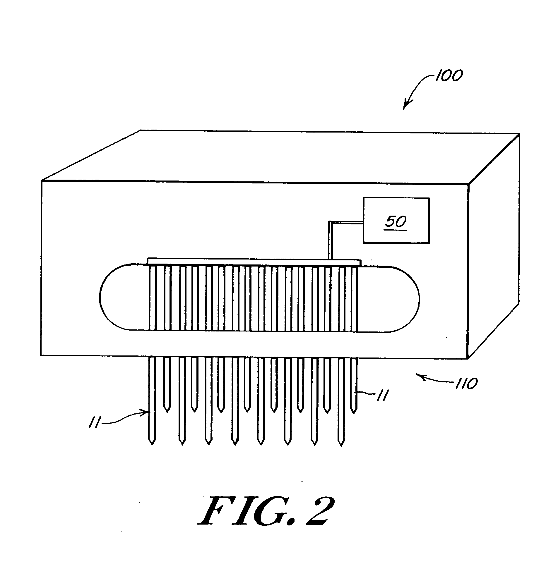
A droplet dispensing system for forming and dispensing droplets of a liquid sample is provided. The droplet dispensing system is fabricated on the tip of a dispensing pin. The tip of the dispensing pin includes a droplet ejection nozzle, a filling channel, a chamber and an actuator for ejecting droplets on demand. The system further includes a holder for mounting the dispensing pin. The holder also contains a control circuit for activating the actuator.

Description

REFERENCE TO RELATED APPLICATIONS [0001] This application is a divisional application of U.S. application Ser. No. 10 / 029,108, which claims priority to U.S. Provisional Patent Application No. 60 / 325,040, entitled “Droplet Dispensing System” filed Sep. 25, 2001, and is related to U.S. patent application Ser. No. 10 / 028,852, entitled “Microfluidic System Including a Virtual Wall Fluid Interface Port for Interfacing Fluids with the Microfluidic System”, filed Jun. 20, 2002, U.S. patent application Ser. No. 10 / 027,484, entitled “Microfluidic System Including a Virtual Wall Fluid Interface Port for Interfacing Fluids with the Microfluidic System”, filed Jun. 20, 2002, U.S. patent application Ser. No. 10 / 027,516, entitled “Microfluidic System Including a Virtual Wall Fluid Interface Port for Interfacing Fluids with the Microfluidic System”, filed Jun. 20, 2002; U.S. patent application Ser. No. 10 / 027,171, entitled “Microfabricated Two-Pin Liquid Sample Dispensing System”, filed Jun. 20, 2...

Claims


Application Information

Patent Timeline
Patent Type & Authority Applications(United States)
IPC IPC(8): B01L3/02C12Q1/00G01N27/447G01N35/10
CPCB01L3/0244B01L3/0248B01L3/0268B01L2200/143B01L2200/147Y10T436/2575C12Q1/00G01N27/447G01N2035/1037Y10T436/119163B01L2400/0439
Inventor GILBERT, JOHN
Owner CYTONOME INC
Why Eureka
Try Eureka