Mobile station, mobile communication system, and cell selection method

a cell selection and mobile communication technology, applied in the field of mobile stations, can solve the problems of inability of mobile stations to select the optimal cell for communication, inability to consider cell selection in the aforementioned prior art, etc., and achieve the effect of stabilizing good communication quality and not deteriorating the communication quality of the serving cell

Inactive Publication Date: 2005-02-17
NTT DOCOMO INC
View PDF5 Cites 129 Cited by
  • Summary
  • Abstract
  • Description
  • Claims
  • Application Information

AI Technical Summary

Benefits of technology

According to these aspects of the invention, the cell reselection condition is changed according to the types of the current and neighboring cells. For example, where the mobile station is camped on an indoor cell, the continuous residence in the serving cell is more likely to stabilize good communication quality, than where the mobile station moves into an outdoor cell. In this case, therefore, when the received level of the se...

Problems solved by technology

However, the cell selection in the aforementioned prior art involves no consideration to whether a cell as a candidate for a resele...

Method used


Image

  • Mobile station, mobile communication system, and cell selection method
  • Mobile station, mobile communication system, and cell selection method
  • Mobile station, mobile communication system, and cell selection method

Examples


first embodiment

The first embodiment of the present invention will be described below in detail with reference to the drawings.

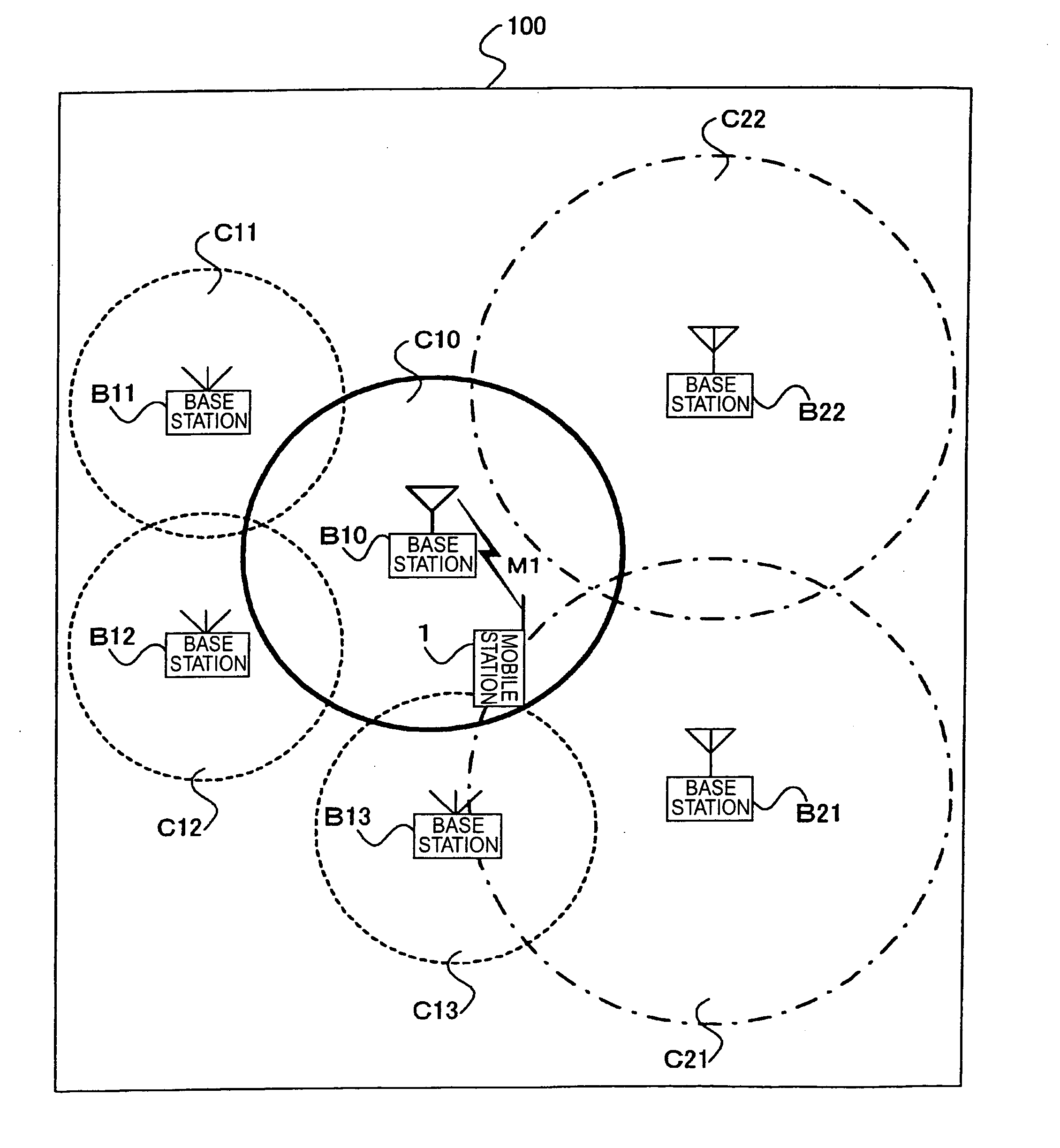
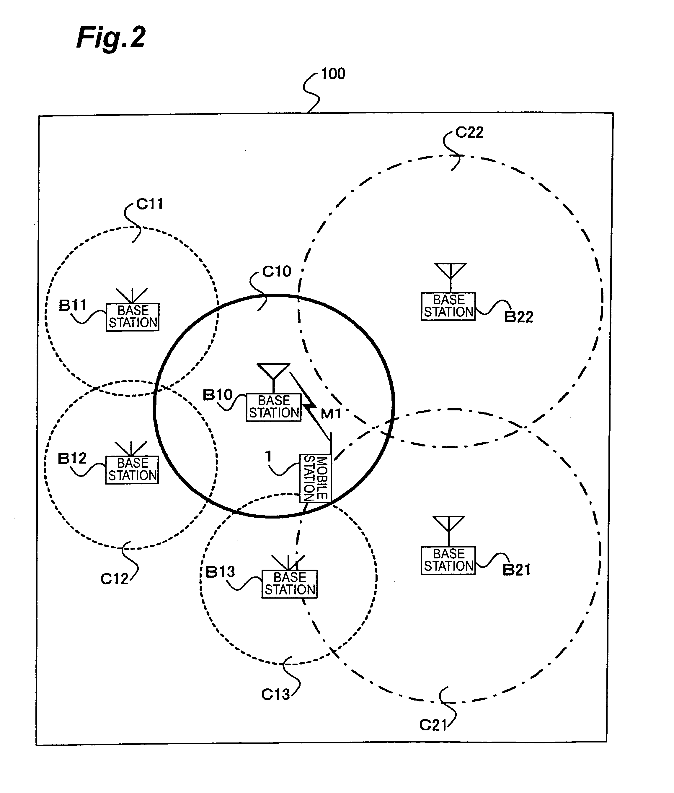
FIG. 2 is a conceptual diagram showing a configuration of a mobile communication system in the present embodiment. As shown in FIG. 2, mobile communication system 100 is comprised of mobile station 1, base station B10, base stations B11-B13, and base stations B21-B22. Mobile station 1 is camped on cell C10 established by base station B10. Cells C11, C12, and C13 established by the respective base stations B11, B12, and B13 exist as indoor cells neighbor to cell C10, and cells C21 and C22 established by the respective base stations B21 and B22 exist as outdoor cells neighbor to cell C10. In FIG. 2, the indoor cells are indicated by dashed lines and the outdoor cells by chain lines.

Base station B10 notifies mobile station 1 of information indicating that cells C11-C13 and cells C21, C22 exist as neighboring cells and, in addition thereto, information (identification infor...

second embodiment

Subsequently, the second embodiment of the present invention will be described with reference to FIGS. 11 to 14. Since the mobile communication system in the second embodiment includes the components and processes common to those in the mobile communication system in the first embodiment, only differences from the first embodiment described above will be detailed below.

Specifically, the cell selection technology in the first embodiment involved no consideration to existence of mobile cells as one of the cell forms. A mobile cell is constructed by a moving object such as a train, a bus, or the like, and is a cell having a mechanism capable of maintaining communication between a mobile station in the cell and the mobile communication system while keeping the configuration even with movement in the mobile communication system. A mobile base station communicates through a radio link with external base stations (outdoor cells and indoor cells) and a mobile station in the mobile cell i...


PUM


Abstract

In mobile communication system 100 according to the present invention, mobile station 1 is camped on cell C10 established by base station B10. In the cell C10, there exist indoor cells C11-C13 and outdoor cells C21, C22 as neighboring cells. Mobile station 1 measures received levels of cells C10-C13, C21, C22 and determines cell types of the respective cells, i.e., whether each cell is an indoor cell or not, based on broadcast information M1. Mobile station 1 selects a cell as a reselection target on the basis of the received levels and cell types.

Description

BACKGROUND OF THE INVENTION 1. Field of the Invention The present invention relates to a mobile station, a mobile communication system, and a cell selection method. 2. Related Background Art Conventionally, when a mobile station selects a cell as a reselection target, the mobile station measures a received level of a signal from a base station currently under communication therewith or a base station of a cell where the mobile station is camped, and received levels from base stations of neighboring cells. The mobile station compares the received levels and selects as a target cell a cell with the maximum received level from its base station, based on the result of the comparison (e.g., reference is made to Patent Document 1 and Patent Document 2). The conventional cell selection method will be briefly described below with reference to FIG. 1. As shown in FIG. 1, mobile station 10 is camped on a cell C0 established by base station B0, and cells C1, C2, and C3 exist as cells neig...

Claims


Application Information

Patent Timeline
IPC IPC(8): H04W36/04H04W36/30
CPCH04W36/30H04W36/04
Inventor YAMASHITA, TAKESHIMATSUKI, HIDEOHAGIWARA, JYUNICHIROUKAYAMA, HIDETOSHIUMEDA, NARUMI
Owner NTT DOCOMO INC
Why Eureka
Try Eureka