Tyre for motorcycle

a technology for motorcycles and tyres, applied in the field of structures, can solve the problems of shortened life of tyres, and achieve the effect of preventing partial wear and maintaining performance for a long period of tim

Inactive Publication Date: 2005-02-24
SUMITOMO RUBBER IND LTD
View PDF7 Cites 15 Cited by
  • Summary
  • Abstract
  • Description
  • Claims
  • Application Information

AI Technical Summary

Benefits of technology

[0009] The present invention has been made in such a background. It is an object of the present invention to provide a tyre for a motorcycle which can prevent a partial wear and can maintain a performance for a long period of time.

Problems solved by technology

As a result, there is a problem in that the lifetime of the tyre 1 is shortened due to the partial wear.

Method used


Image

  • Tyre for motorcycle
  • Tyre for motorcycle
  • Tyre for motorcycle

Examples


examples

[0054] Next, the effects of the present invention will be described with reference to examples. The present invention should not be construed to be restricted based on the description of the examples.

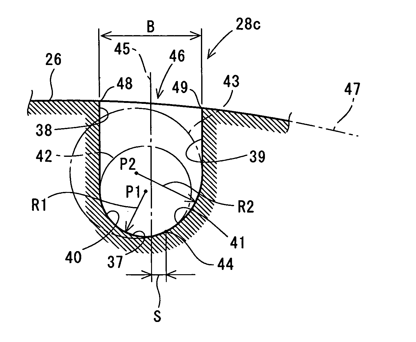
[0055] Referring to the performance of a tyre according to an example of the present invention, Table 1 shows a result obtained by the execution of a comparison test for a comparative example. The size of a tyre according to each of the examples and the comparative example is 120 / 70ZR18M / C(59W)D220FST T / L. In the comparison test, a difference in a tyre wearing way depending on a difference in the shape of the groove of the tyre is measured. The shape of the groove of the tyre is specified by a radius of curvature R1 of a corner portion provided on an inside in an axial direction, a radius of curvature R2 of a corner portion provided on an outside in the axial direction, and the presence of the point of contact of a phantom circle for defining each of the corner portions and a position ...


PUM


Abstract

A radius of curvature (R1) of a corner portion (40) on one side (an inside in an axial direction) of a groove of a tyre (20) is smaller than a radius of curvature (R2) of the other corner portion (41). Both of the radii of curvature (R1) and (R2) are set to be 2 mm or more. A first phantom circle (42) for defining the corner portion (40) is inscribed on a second phantom circle (43) for defining the corner portion (41). A point of contact (44) of the first phantom circle (42) and the second phantom circle (43) is positioned on an outside from the center of a groove (28c). A distance between the center of the groove (28c) and the point of contact (44) is equal to or smaller than one fifth of a width (B) of the groove (28c).

Description

[0001] This application claims priority on Patent Application No. 2003-208310 filed in Japan on Aug. 21, 2003. BACKGROUND OF THE INVENTION [0002] 1. Field of the Invention [0003] The present invention relates to a structure of a tyre to be employed for a motorcycle. [0004] 2. Description of the Related Art [0005] As shown in FIG. 5, in a tyre 1 for a motorcycle (which will be hereinafter referred to as a “tyre”), a tread surface 2 takes such a shape as to be curved outward in a radial direction and a groove 3 is formed on the tread surface 2. The tyre 1 is attached to the motorcycle. When the motorcycle runs, the total weight of a vehicle including the weight of a driver is applied to the tyre 1. Therefore, a portion with which the tyre 1 comes in contact is flattened. [0006] When a state in which the tyre 1 does not come in contact with a ground as shown in FIG. 6(a) is changed to a state in which the tyre 1 comes in contact with the ground as shown in FIG. 6(b), a contact surface ...

Claims


Application Information

Patent Timeline
Patent Type & Authority Applications(United States)
IPC IPC(8): B60C11/03B60C11/04B60C11/13
CPCB60C11/0302B60C11/0309B60C2011/0374B60C2200/10B60C11/1323B60C11/13
Inventor YAMANE, MASAKATSU
Owner SUMITOMO RUBBER IND LTD
Why Eureka
Try Eureka