Fuel pressure adjusting apparatus

a technology of pressure adjustment and fuel, which is applied in the direction of mechanical equipment, liquid fuel feeders, machines/engines, etc., can solve the problems of unstable fuel flow, and achieve the effect of reducing production costs and reducing production costs

Active Publication Date: 2006-10-24
AISAN IND CO LTD
View PDF12 Cites 6 Cited by
  • Summary
  • Abstract
  • Description
  • Claims
  • Application Information

AI Technical Summary

Benefits of technology

[0021]With this configuration, the force-applying member includes the concave portion which supports the valve element, and which is formed such that there is a small gap between the side wall surface of the concave portion and the valve element. Accordingly, even in a case where an axis of the valve element is slightly deviated from an axis of the valve seat, the axis of the valve element is caused to match the axis of the valve seat due to a self-aligning effect. Therefore, it is possible to prevent leakage of the fuel when the valve element closes the communication passage, and to prevent partial wear of the valve element. Also, when the valve element opens the communication passage, the flow of the fuel is separated from the valve element before the flow of the fuel becomes unstable in the vicinity of the low end of the valve element. Therefore, it is possible to prevent occurrence of abnormal noise caused by instability of the valve element, and to prevent a drop in the control pressure at low flow rates.
[0023]With the configuration, since the valve element is a spherical body, it is possible to make the structure of the valve element simple and small, and to cause the fuel to flow out smoothly.
[0025]With the configuration, since the depth of the concave portion is equal to or smaller than a half of the diameter of the valve element, it is possible to easily form the concave portion, and to prevent vibration of the valve element due to the fuel flowing into the concave portion.
[0029]With this configuration, since the communication port is formed in the force-applying member, it is not necessary to provide specific passage means. Therefore, it is possible to reduce the production cost.
[0030]In the first aspect of the invention, the force-applying member may be joined to the casing by crimping. Since the force-applying member is joined to the casing by crimping, the force-applying member can be joined to the casing easily. Therefore, it is possible to reduce the production cost.

Problems solved by technology

Also, when the valve element opens the communication passage, the flow of the fuel is separated from the valve element before the flow of the fuel becomes unstable in the vicinity of the low end of the valve element.

Method used


Image

  • Fuel pressure adjusting apparatus
  • Fuel pressure adjusting apparatus
  • Fuel pressure adjusting apparatus

Examples


Embodiment Construction

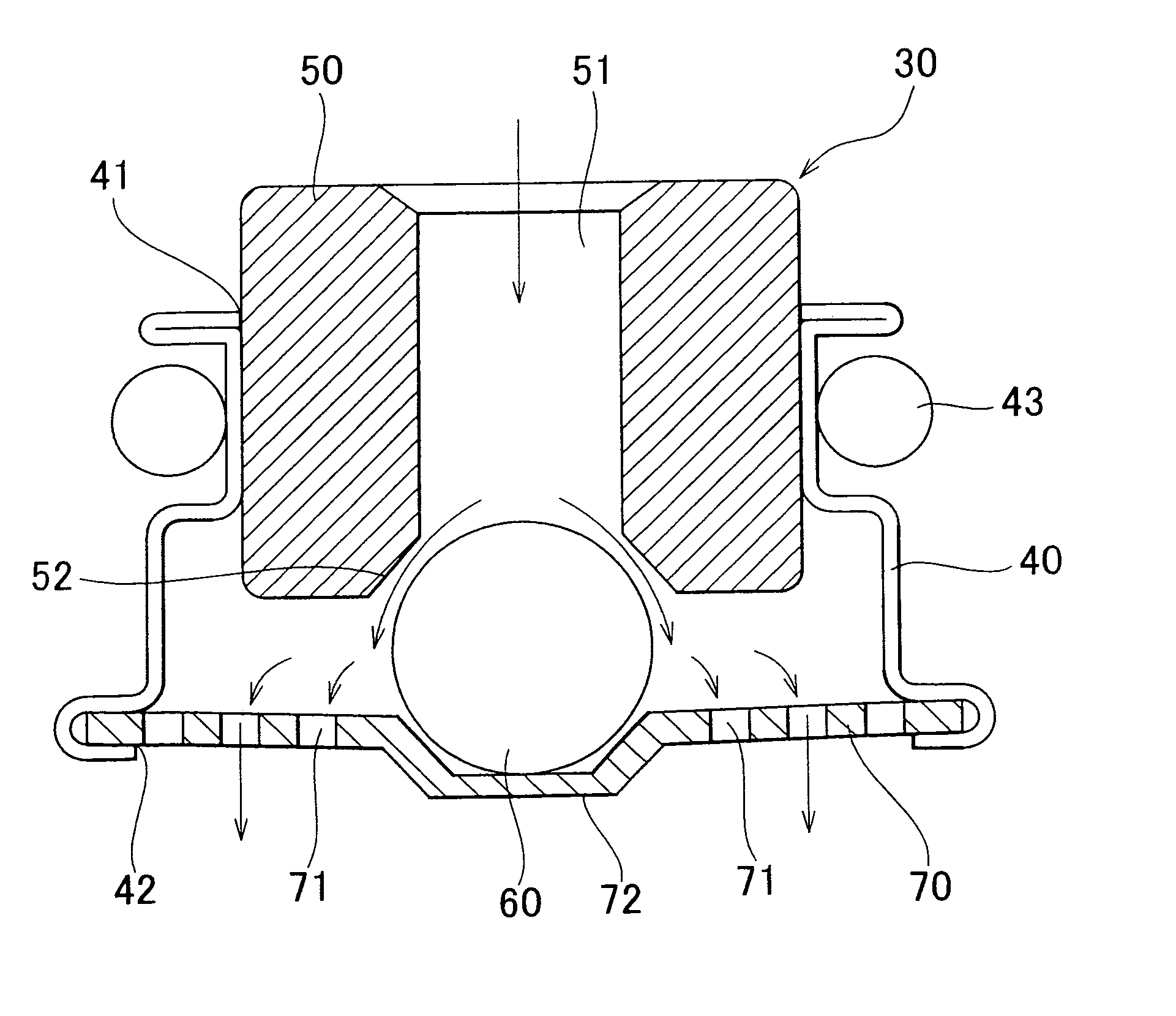
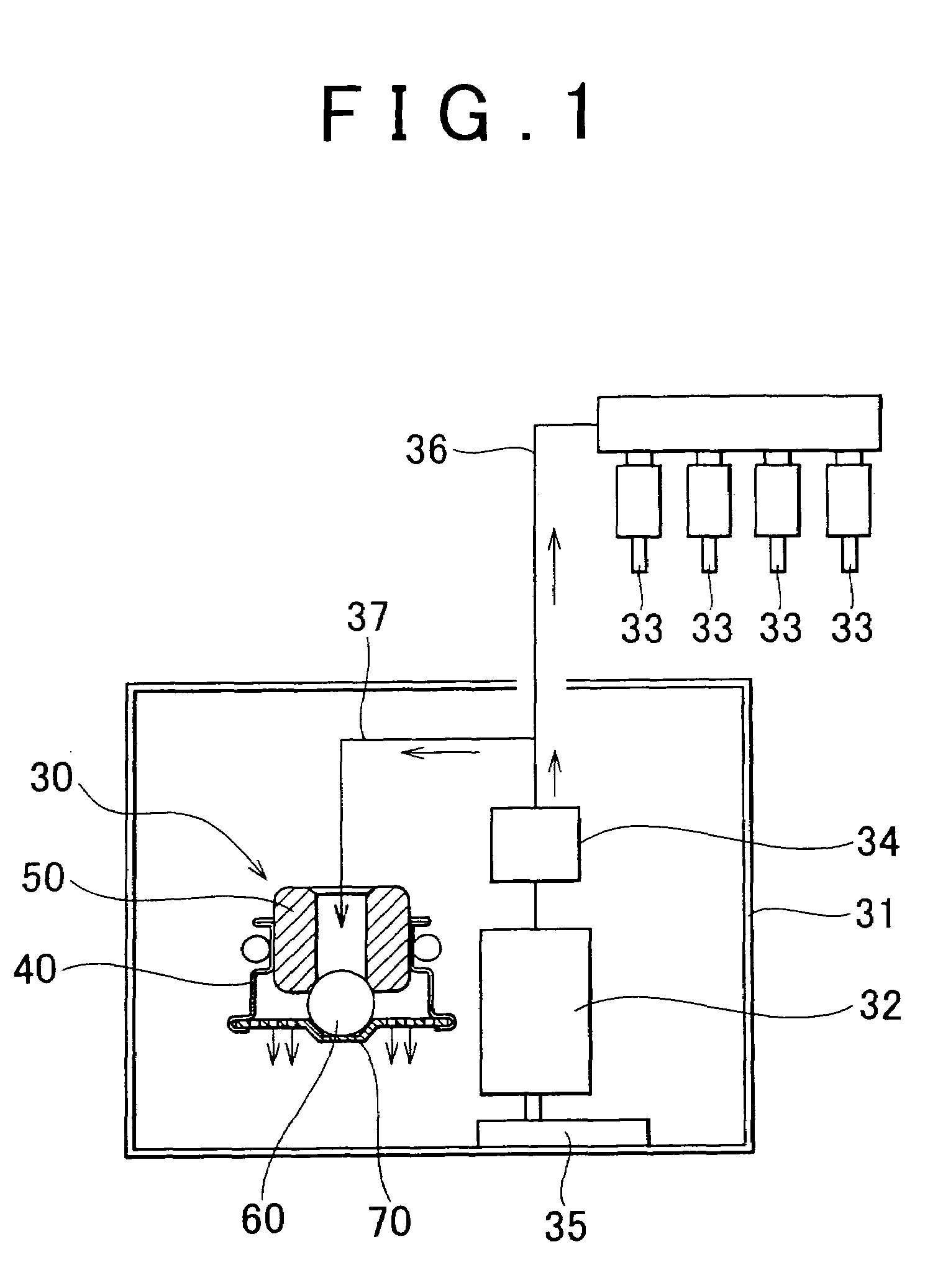
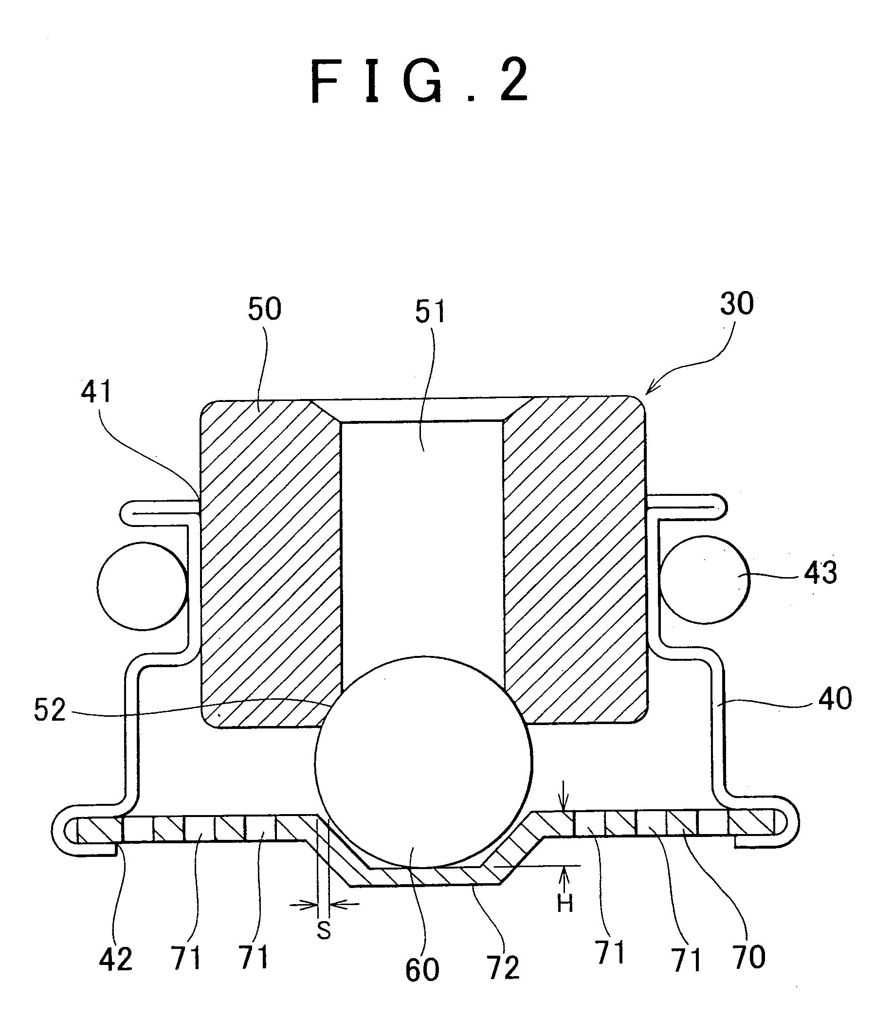
[0041]FIG. 1 is a schematic diagram showing an entire fuel supply system including a fuel pressure adjusting apparatus. FIG. 2 is a cross sectional view showing the fuel pressure adjusting apparatus in which a valve element closes a communication passage. FIG. 3 is a cross sectional view showing the fuel pressure adjusting apparatus in which the valve element opens the communication passage. FIG. 4 shows a plan view showing a leaf spring. FIG. 5 shows a control pressure characteristic with respect to a flow rate of fuel.

[0042]For example, a fuel pressure adjusting apparatus 30 is provided so as to be connected to a fuel passage 36 through which fuel is supplied from a fuel tank 31 of a vehicle to injectors 33 of an internal combustion engine by a fuel pump 32. The fuel pressure adjusting apparatus 30 adjusts a pressure of the fuel supplied to the injectors 33 to a predetermined value. Hereinafter, the in-tank type fuel pressure adjusting apparatus will be described.

[0043]In the fuel...


PUM


Abstract

A fuel pressure adjusting apparatus which includes a casing which includes a fuel introduction port, and a fuel discharge port; and a cylindrical member which is housed in the casing, and which includes a valve seat at an end portion thereof, and a communication passage therein, the communication passage connecting the fuel introduction port to the fuel discharge port; a valve element which is provided on a fuel discharge port-side of the valve element in the casing, and which closes the communication passage when the valve element is seated on the valve seat; and a leaf spring which is provided at the fuel discharge port, and which applies force to the valve element in a direction toward the valve seat. The leaf spring includes a concave portion which supports the valve element, and which is formed such that there is a gap between the concave portion and the valve element.

Description

INCORPORATION BY REFERENCE[0001]The disclosure of Japanese Patent Application No. 2004-219565 filed on Jul. 28, 2004 including the specification, drawings and abstract is incorporated herein by reference in its entirety.BACKGROUND OF THE INVENTION[0002]1. Field of the Invention[0003]The invention relates to a fuel pressure adjusting apparatus which adjusts a pressure of fuel supplied from a fuel tank to an injector of an internal combustion engine by a fuel pump.[0004]2. Description of the Related Art[0005]Japanese Patent Application Publication No. JP(A) 2000-45897 discloses a fuel pressure adjusting apparatus shown in FIG. 8. In the fuel pressure adjusting apparatus 1, an inside of a casing 2 is divided into an atmosphere chamber 4 and a fuel chamber 5 by a diaphragm 3, and a valve element 6 is provided in the diaphragm 3.[0006]When a pressure of fuel introduced into the fuel chamber 5 through a fuel introduction port 8 becomes equal to or higher than a predetermined value, the di...

Claims


Application Information

Patent Timeline
Patent Type & Authority Patents(United States)
IPC IPC(8): F02M69/54F02M51/00
CPCF02M55/02F02M63/0012F02M63/0225
Inventor ENDOH, TADAOARAI, KATSUMIKONISHI, MASAAKI
Owner AISAN IND CO LTD
Why Eureka
Try Eureka