Paper discharge device and image forming apparatus having the same

Inactive Publication Date: 2005-12-01
S PRINTING SOLUTION CO LTD
View PDF5 Cites 7 Cited by
  • Summary
  • Abstract
  • Description
  • Claims
  • Application Information

AI Technical Summary

Benefits of technology

[0016] An aspect of the present invention is to solve at least the above problems and/or disadvantages and to provide at least the advantages described below. Accordingly, an aspect of the present invention is to provide

Problems solved by technology

Therefore, due to the humidity differential and a variety of other factors, the print paper often wrinkles.
Curling of the print paper causes difficulties when transferring the print paper.
As a result, paper jams occur and the print paper blocks the transfer path and prev

Method used


Image

  • Paper discharge device and image forming apparatus having the same
  • Paper discharge device and image forming apparatus having the same
  • Paper discharge device and image forming apparatus having the same

Examples


first embodiment

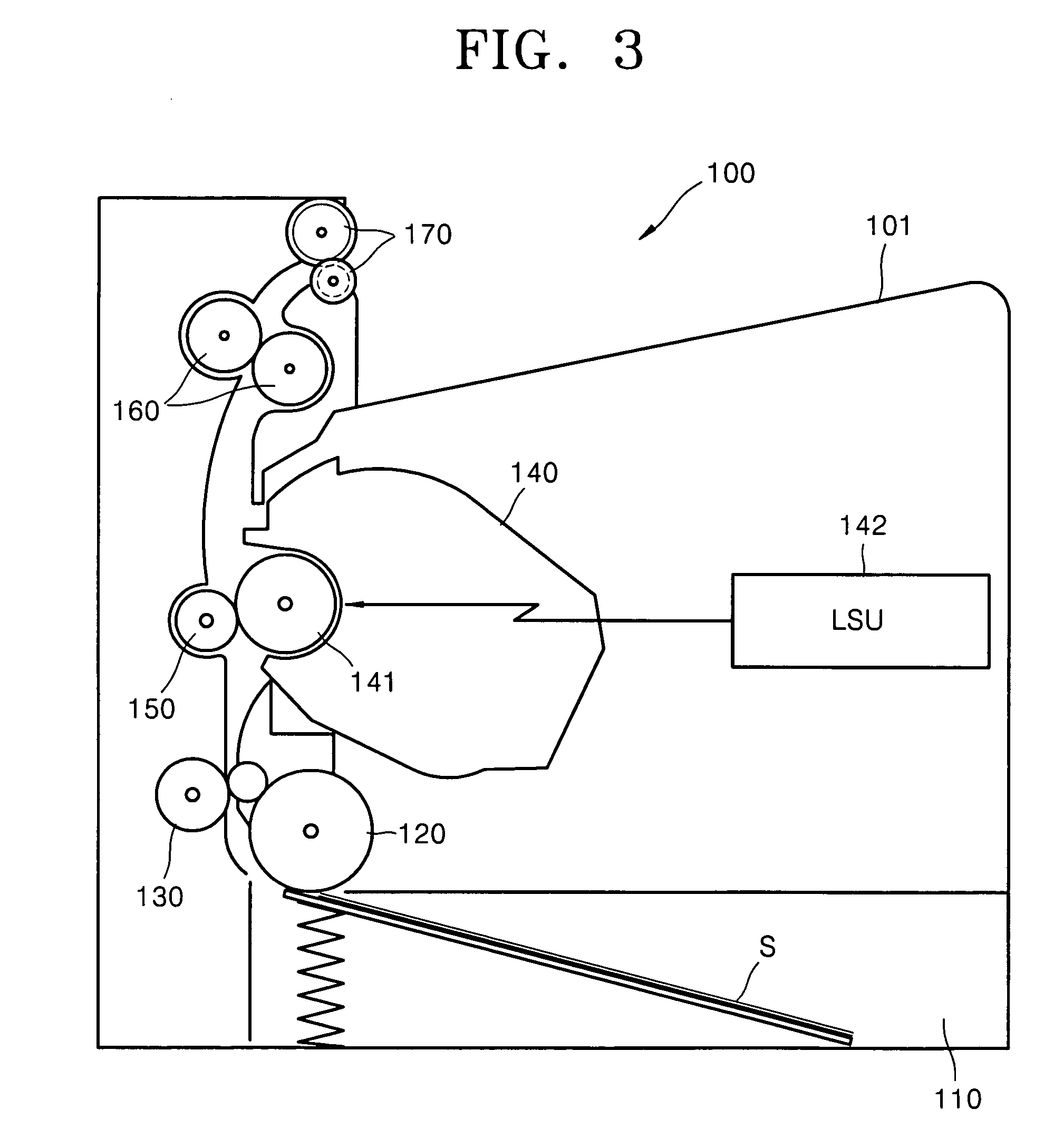
[0031]FIG. 3 is a side view of the structure of an image forming apparatus adopting a paper discharge device according to the present invention,

[0032]FIG. 4 is a front view of the paper discharge device of FIG. 3, and FIG. 5 is a plane view of the paper discharge device of FIG. 3.

[0033] Referring to FIG. 3, a paper cassette 110, on which print paper S is mounted, is attachable and detachable to and from an image forming apparatus 100. Moreover, the paper cassette 110 is installed under the main body 101. A pickup roller 120 picks up print paper S sheet by sheet and is installed on the paper cassette 110.

[0034] The image forming apparatus 100 comprises a developing device 140, an exposure device 142, a transfer roller 150, a fusing device 160, and a paper discharge unit 170. Each component is disposed along a transfer path of the print paper S.

[0035] The developing device 140 supplies toner as a developing agent to an electrostatic latent image formed on a photosensitive medium to...

second embodiment

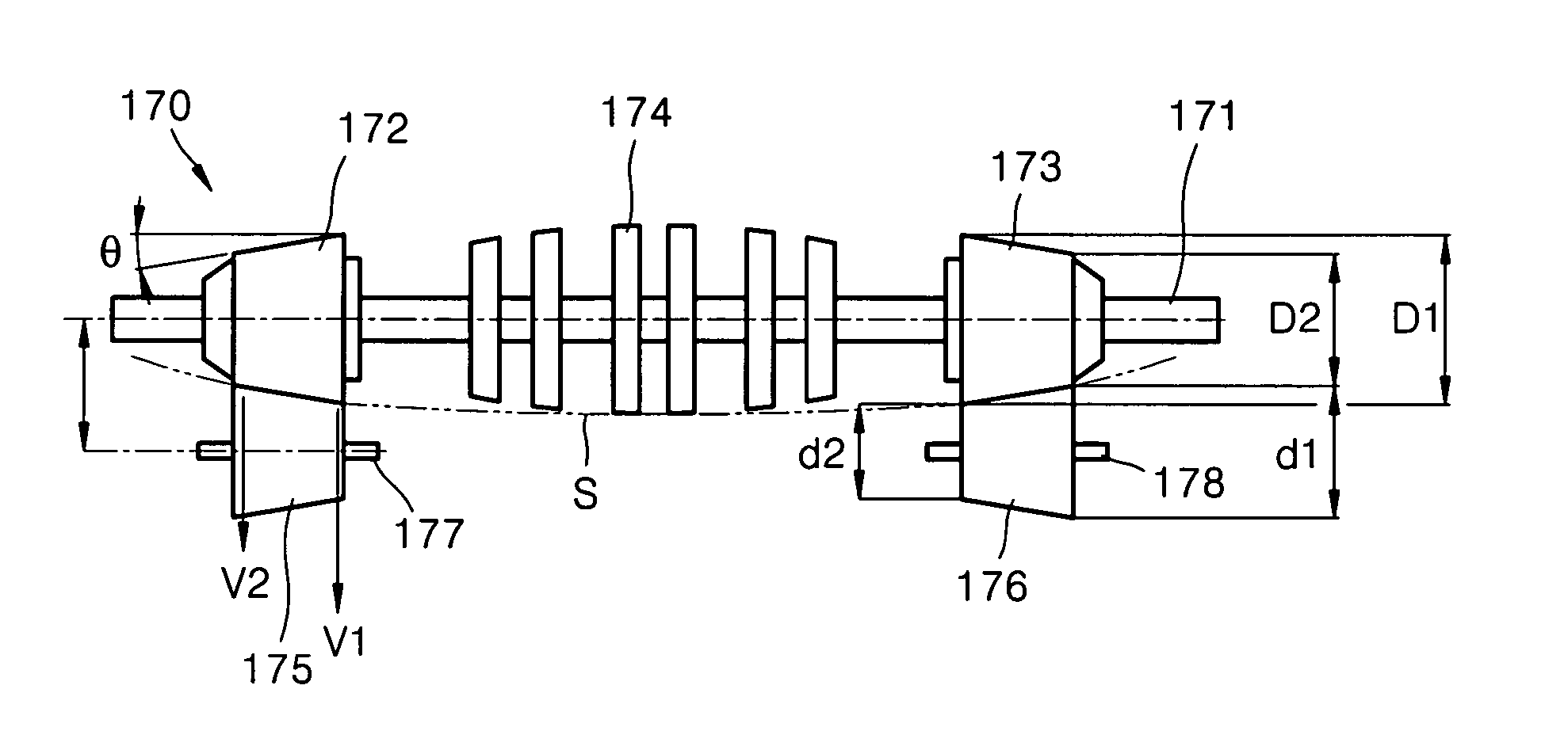
[0046]FIG. 6 is a front view of a paper discharge device in accordance with the present invention. FIG. 7 is a plan view of the paper discharge device of FIG. 6.

[0047] Referring to FIGS. 6-7, a paper discharge device 180 discharges the print paper S on which the toner image is fused by the fusing device 160 (see FIG. 3) to the outside of the main body 101 (see FIG. 3). As shown in FIG. 6, the paper discharge device 180 comprises paper discharge rollers 182, 183 and idle rollers 185, 186 which face the paper discharge rollers 182, 183.

[0048] An intermediate roller 184 is installed in the middle portion of a paper discharge shaft 181, and the paper discharge rollers 182, 183 are installed at both sides of the intermediate roller 184. The intermediate roller 184 has a tapered structure in which the diameter becomes gradually smaller at one end. Therefore, the middle portion of the discharged print paper S is pressed concavely to prevent wrinkling.

[0049] Each of the paper discharge ro...

third embodiment

[0054]FIG. 8 is a front view of a paper discharge device in accordance with the present invention. FIG. 9 shows a kicker of FIG. 8.

[0055] Referring to FIGS. 8-9, the configuration of the paper discharge device is the same as that of the paper discharge device 180 of FIGS. 6-7. The only difference is the discharge unit 194 has a plurality of kickers 195 formed along a circumferential direction to contact ends of the print paper S at both sides of the idle rollers 185, 186.

[0056] When the ends of the print paper S pass through a nip between each of the paper discharge rollers 182, 183 and each of the idle rollers 185 and 186, the discharge unit 194 allows the kickers 195 to hit the ends of the print paper S. Thus, the print paper S is smoothly discharged to the outside.

[0057] As described above, the paper discharge device according to the present invention has the following advantages. First, a paper discharge roller and an idle roller contact each other uniformly and apply uniform ...


PUM


Abstract

A paper discharge device and an image forming apparatus having the same are provided. In the paper discharge device, the paper discharge roller has a non-uniform diameter extending in a longitudinal direction and the idle roller contacts with the paper discharge roller in the longitudinal direction of the paper discharge roller so that the print paper unfolds and discharges utilizing a velocity differential at a nip between the paper discharge roller and the idle roller.

Description

BACKGROUND OF THE INVENTION [0001] This application claims the benefit under 35 U.S.C. § 119(a) of Korean Patent Application No. 10-2004-0037251, entitled “Paper Discharge Device and Image Forming Apparatus Having the Same,” filed on May 25, 2004, the entire disclosure of which is incorporated hereby incorporated by reference. [0002] 1. Field of the Invention [0003] The present invention relates to an image forming apparatus. More particularly, the present invention relates to a paper discharge device capable of stably discharging paper, on which an image is formed, in an unfolded state. [0004] 2. Description of the Related Art [0005] In general, an image forming apparatus such as a printer produces electrostatic latent images on a photosensitive drum in response to print data. The image forming apparatus utilizes an exposure unit that supplies toner as a developing agent to form the electrostatic latent images as toner images, transfers the toner images to print paper, and fuses th...

Claims


Application Information

Patent Timeline
IPC IPC(8): G03G15/00
CPCG03G15/6552F25D11/04F25D29/005F25D23/026A23B4/06
Inventor AHN, BYUNG-SUN
Owner S PRINTING SOLUTION CO LTD
Why Eureka
Try Eureka