Grinding apparatus and method of controlling grinding apparatus

a grinding apparatus and grinding wheel technology, applied in the direction of grinding spindles, grinding machine components, manufacturing tools, etc., can solve the problems of affecting the life of grinding wheels, affecting the operation of grinding wheels, so as to lighten the impact force and make grinding wheels wear hard to occur

Inactive Publication Date: 2009-02-12
JTEKT CORP
View PDF7 Cites 7 Cited by
  • Summary
  • Abstract
  • Description
  • Claims
  • Application Information

AI Technical Summary

Benefits of technology

[0013]It is therefore an object of the invention to provide a grinding apparatus capable of lightening an impact force and making grinding wheel wear hard to occur if the axial position of a groove deviates when the groove formed on the peripheral surface of a workpiece is worked on, and to provide a method of controlling the grinding apparatus.
[0027]Before the casing moves radially and the grinding wheel comes in contact with the workpiece, the stiffness value of the radial magnetic bearings is set to the initialization value lower than the value at the usual grinding time and after the grinding surface of the grinding wheel comes in contact with the workpiece, the stiffness value of the radial magnetic bearings is set to a value higher than the initialization value for grinding the workpiece. Thus, the grinding wheel comes in contact with the workpiece in a state in which the stiffness value of the radial magnetic bearings is low; when the grinding wheel comes in contact with the workpiece, it can get away radially. Thus, the impact force produced when the grinding wheel comes in contact with the workpiece is lightened.
[0037]An external force in the radial direction does not act on the grinding wheel or the grinding wheel spindle before the grinding wheel comes in contact with the workpiece. Thus, in the integration operation section of the bearing controller, the integration output is smaller than the reference value, the integration constant is set to the initialization value lower than the value at the usual grinding time, and the stiffness value in the radial direction is set to a value lower than the value at the usual grinding time. When the grinding wheel comes in contact with the workpiece, an external force in the radial direction acts on the grinding wheel and the grinding wheel spindle. Thus, in the integration operation section, the integration output becomes larger than the reference value and accordingly the integration constant becomes larger than the initialization value and the stiffness value of the radial magnetic bearings becomes larger than the value before the grinding wheel comes in contact with the workpiece. Thus, the impact force produced when the grinding wheel comes in contact with the workpiece is lightened as with the first aspect of the invention.
[0041]If the groove R is formed at the correct position by pre-working and the groove R and the grinding wheel G match in the axial position as in FIG. 6A, when the casing 4 is moved radially and the grinding wheel G is brought close to the workpiece W, the grinding surface S of the grinding wheel comes in contact with the whole groove R almost at the same time. After the grinding surface S of the grinding wheel comes in contact with the whole groove R, the stiffness value of the radial magnetic bearings is set to a value higher than the initialization value. When the casing 4 is moved radially, the grinding surface S of the grinding wheel comes in contact with the whole groove R almost at the same time and moreover the stiffness value of the radial magnetic bearings at this time is lower than the value at the usual grinding time and the grinding wheel can get away in the axial direction. Thus, the impact is lightened and the grinding surface S does not locally wear (or chip).
[0042]If the position of the groove R by pre-working shifts axially to the left of the drawing as in FIG. 6B, when the casing 4 is moved radially and the grinding wheel G is brought close to the workpiece W, first only the right edge of the groove R comes in contact with the grinding surface S of the grinding wheel. However, the stiffness value of the radial magnetic bearings at this time is lower than the value at the usual grinding time and the grinding wheel can get away in the radial direction. Thus, the impact is lightened and the grinding surface S does not locally wear (or chip).
[0047]According to the third aspect of the invention, the impact force produced when the grinding wheel comes in contact with the portion of the groove of the workpiece is lightened as described above and moreover if the axial position of the groove deviates, grinding wheel wear is hard to occur and occurrence of local wear of the grinding wheel can be prevented.

Problems solved by technology

At this time, if the axial position of the groove formed on the inner peripheral surface of the workpiece in the preceding step does not involve any error, an impact force only acts; however, if an error occurs and the axial position of the groove deviates axially from the correct position, not only an impact force, but also so-called grinding wheel wear of extreme wearing (or chip) of a part of the grinding surface of the grinding wheel occurs and the grinding wheel life is shortened.
In addition to finishing grinding of the raceway groove on the inner peripheral surface of the outer ring, to grind a groove formed on the cylindrical peripheral surface (inner peripheral surface or outer peripheral surface) of the workpiece, a similar problem is involved.

Method used


Image

  • Grinding apparatus and method of controlling grinding apparatus
  • Grinding apparatus and method of controlling grinding apparatus
  • Grinding apparatus and method of controlling grinding apparatus

Examples


Embodiment Construction

[0064]Referring now to the accompanying drawings, there is shown an embodiment of the invention.

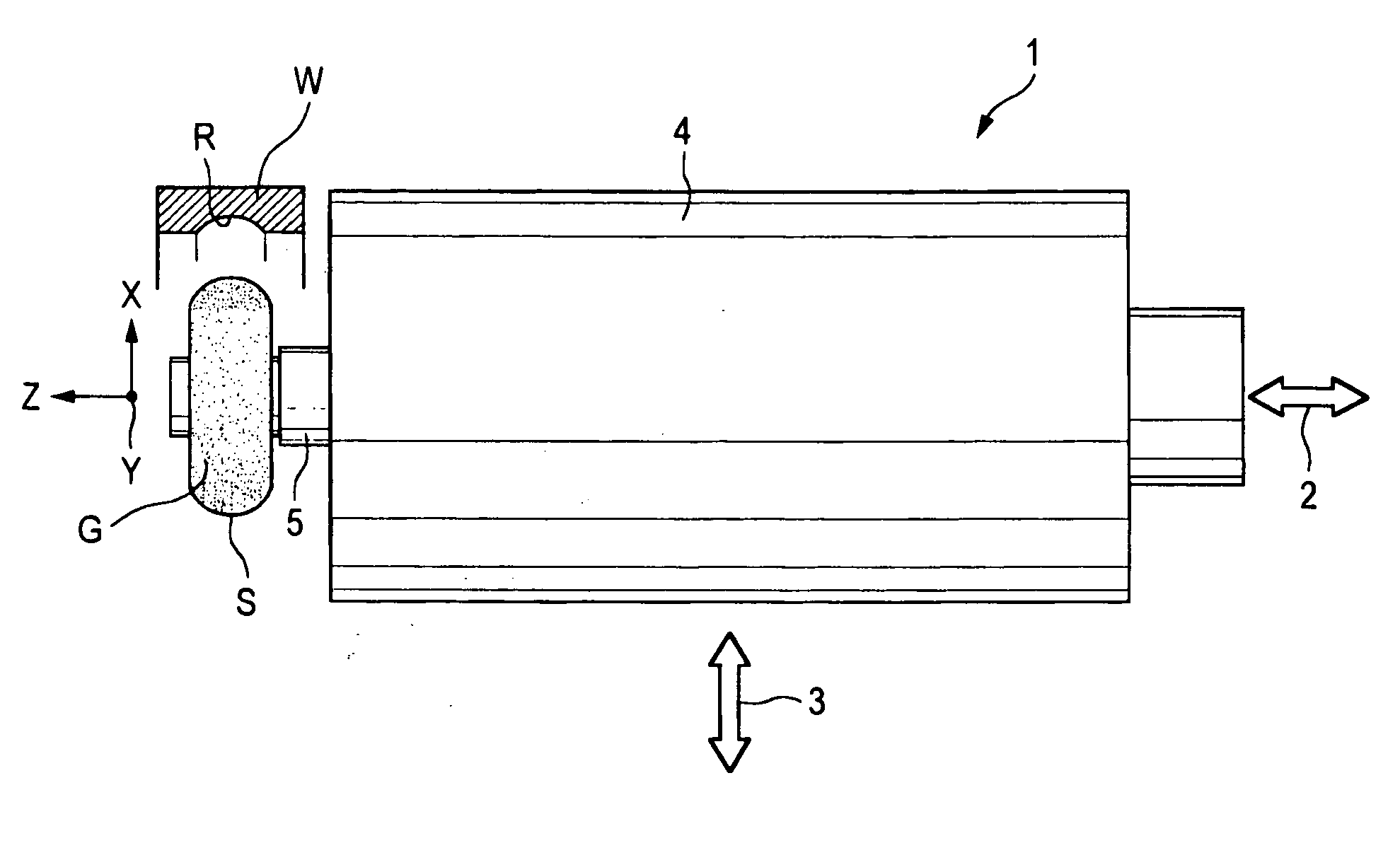
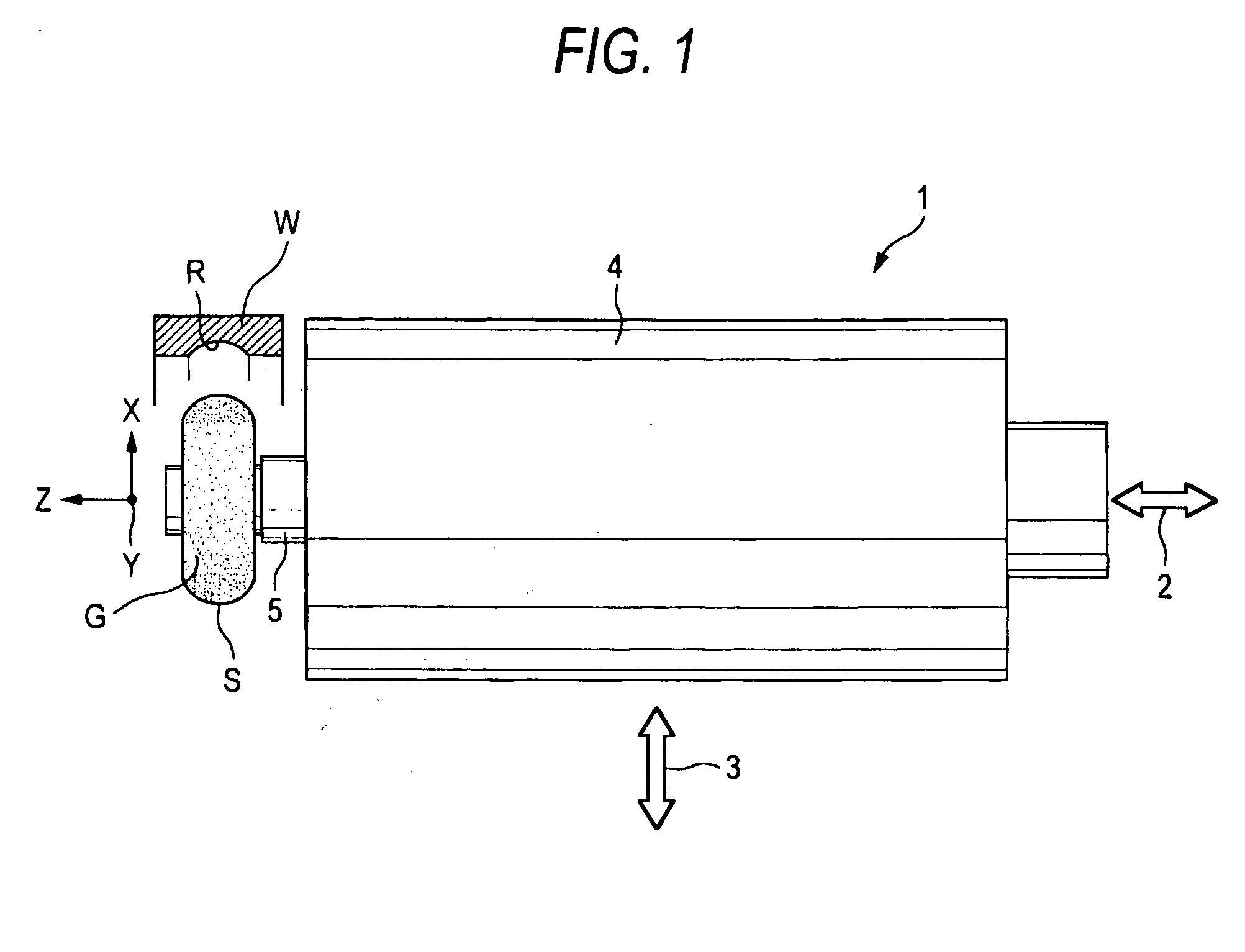
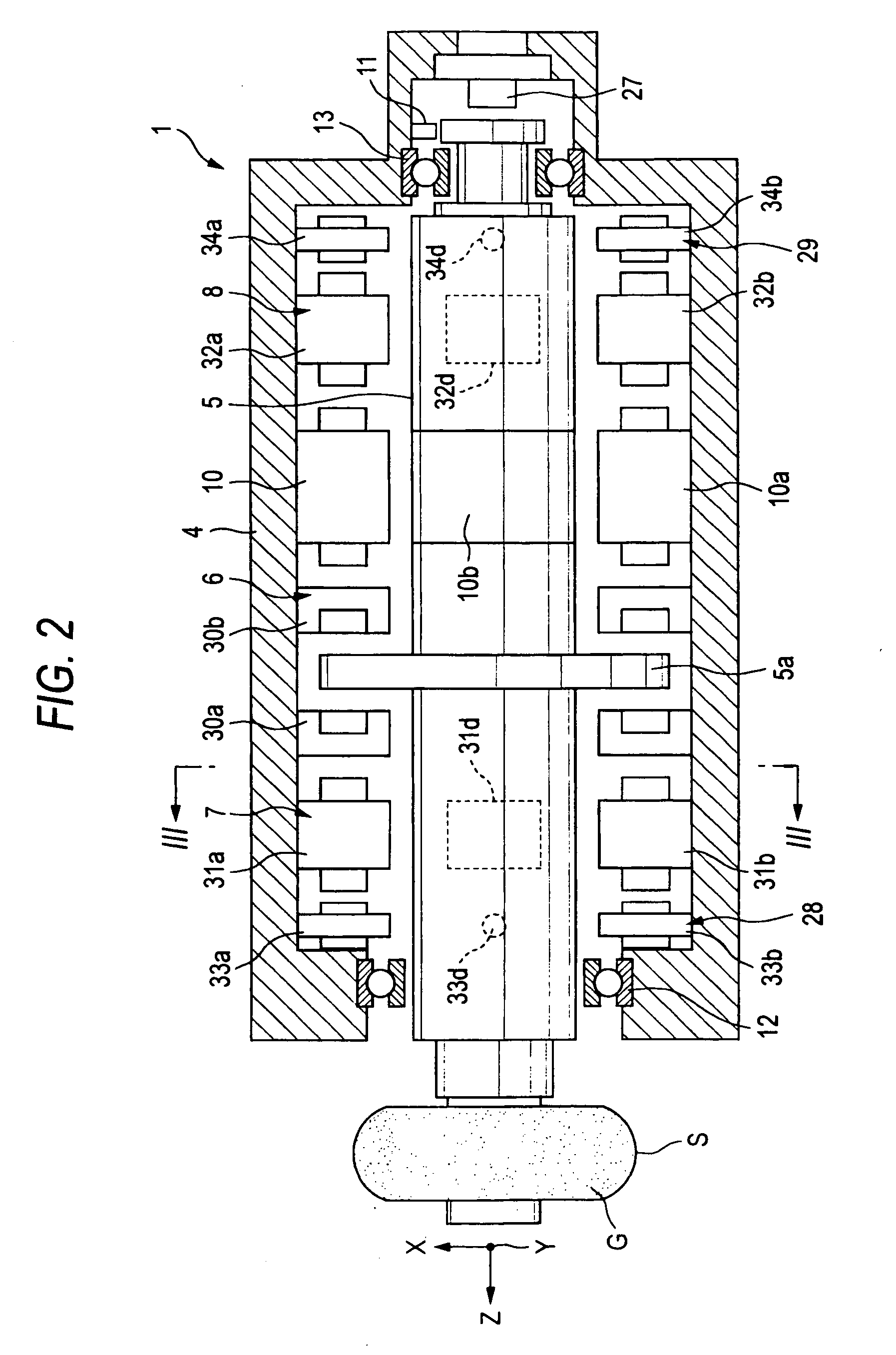
[0065]FIG. 1 is a plan view to show a portion of a magnetic bearing spindle unit of the main part of a grinding apparatus, FIG. 2 is an enlarged sectional view of FIG. 1, FIG. 3 is a sectional view taken on line III-III in FIG. 2, and FIG. 4 is a block diagram to show the main part of the electric configuration of the spindle unit. The surface of the plane of the drawing of each of FIGS. 1 and 2 is the top, the rear of the plane of the drawing is the bottom, the upper side of the plane of the drawing is the back, the lower side of the plane of the drawing is the front, the left of the plane of the drawing is the grinding wheel side, and the right of the plane of the drawing is the grinding wheel opposite side. The top and bottom of the plane of the drawing of FIG. 3 are the top and bottom (up and down), the right is the back, and the left is the front.

[0066]Although not shown in detail in...


PUM


Abstract

A grinding wheel formed on an outer peripheral surface with a grinding surface is attached to a grinding wheel spindle supported by axial active magnetic bearings and radial active magnetic bearings in a noncontact manner axially and radially and rotated by an electric motor. A casing is axially positioned and then is radially moved and a ground part of a workpiece is ground. Before the casing moves radially and the grinding wheel comes in contact with the workpiece, the stiffness value of the radial magnetic bearings is set to an initialization value lower than a value at the usual grinding time and after the grinding surface of the grinding wheel comes in contact with the workpiece, the stiffness value of the radial magnetic bearings is set to a value higher than the initialization value for grinding the workpiece.

Description

BACKGROUND OF THE INVENTION[0001]This invention relates to a grinding wheel for grinding a workpiece on a grinding surface of the outer peripheral surface of the grinding wheel attached to a grinding wheel spindle and in particular to a grinding apparatus adapted to grind a groove formed on a cylindrical peripheral surface of a workpiece, such as a raceway groove formed on the inner peripheral surface of an outer ring of a ball bearing, for example, using a grinding wheel formed on the outer peripheral surface with a center-high grinding surface, and relates to a method of controlling the grinding apparatus.[0002]An internal cylindrical grinding machine is known as a grinding apparatus for performing finishing grinding of a raceway groove formed on the inner peripheral surface of an inner ring of a ball bearing or the inner peripheral surface of an outer ring.[0003]In a usual internal cylindrical grinding machine, a grinding wheel formed on the outer peripheral surface with a grindi...

Claims


Application Information

Patent Timeline
Patent Type & Authority Applications(United States)
IPC IPC(8): B24B51/00B24B7/00B24B19/06B24B41/04
CPCB24B49/00B24B41/044
Inventor KAMENO, HIRONORIKUBO, ATSUSHIISHIGAMI, TAKAYUKI
Owner JTEKT CORP
Why Eureka
Try Eureka