Grinding apparatus

a grinding wheel and grinding surface technology, applied in the direction of gear teeth, grinding spindles, grinding spindles, etc., can solve the problems of extremely worn grinding surface of grinding wheel, shortened life of grinding wheel, etc., and achieve the effect of preventing local wear of grinding wheel

Inactive Publication Date: 2008-09-25
JTEKT CORP
View PDF13 Cites 8 Cited by
  • Summary
  • Abstract
  • Description
  • Claims
  • Application Information

AI Technical Summary

Benefits of technology

[0009]An object of the invention is to solve the aforementioned problems and to provide a grinding apparatus configured so that a grinding wheel wear is hard to occur even when an axial position of a groove formed in a peripheral surface of a work is deviated.
[0023]In a case where the groove is formed at a correct position by the preprocessing, and where the position of the groove coincides with that in the axial direction of the grinding wheel, the grinding surface of the grinding wheel substantially simultaneously touches the entire groove when the casing is radially moved so as to cause the grinding wheel to come close to the work. Then, the stiffness value of the axial magnetic bearing is set back to the normal value after it is detected that the grinding surface S of the grinding wheel touches the entire groove, and that the grinding of the entire groove is started. When the casing is radially moved, the grinding surface of the grinding wheel substantially simultaneously touches the entire groove. Accordingly, the local wear of the grinding surface of the grinding wheel is not caused.
[0037]In a case where the groove is formed at a correct position by the preprocessing, and where the position of the groove coincides with that in the axial direction of the grinding wheel, the grinding surface of the grinding wheel substantially simultaneously touches the entire groove when the casing is radially moved so as to cause the grinding wheel to come close to the work. Thus, when the grinding wheel touches the work, the wheel spindle is not displaced axially with respect to the casing, so that grinding is performed while the wheel spindle remains supported at the normal target position. Further, when the grinding wheel touches the work, the grinding surface of the grinding wheel substantially simultaneously touches the entire groove. Accordingly, the local wear of the grinding surface of the grinding wheel is not caused.
[0038]In a case where the position of the groove formed by the preprocessing is shift leftwardly, first, only the right-side edge of the groove touches the grinding surface of the grinding wheel when the casing is radially moved so as to cause the grinding wheel to come close to the work. Consequently, the wheel spindle is subjected to a leftward force and is moved leftwardly. Thus, the axial levitation target position of the wheel spindle is changed from the normal target position to a left-side position. Further, after the casing comes not to axially move with respect to the wheel spindle when the grinding wheel touches the work, the axial levitation target position of the wheel spindle is set back to the normal target position. Accordingly, the grinding wheel can be prevented from grinding only the edge of the groove. Thus, the local wear of the grinding surface does not occur.
[0041]In this case, even when the position of the groove formed in the preprocessing is axially shifted and when only an edge of the groove touches the grinding surface of the grinding wheel, the wheel spindle moves away, similarly to the case of the first aspect of the invention. Consequently, the local wear of the grinding surface of the grinding wheel can more effectively be prevented.
[0042]As described above, according to the grinding apparatus of the invention, even when the axial position of a groove formed in a peripheral surface of a work is deviated, a grinding wheel wear is difficult to occur. Consequently, the local wear of the grinding wheel can be prevented.

Problems solved by technology

Thus, the conventional internal cylindrical grinding machine has the following problems that have occurred when grinding a raceway groove of the outer ring.
However, in a case where an error in the axial position exists, and where the axial position of the groove is deviated from a correct axial position, a part of the grinding surface of the grinding wheel is extremely worn away.
That is, what is called a grinding wheel wear occurs, so that the life of the grinding wheel is shortened.
Similar problems occur in the case of grinding a groove formed in a cylindrical peripheral surface (i.e., an inner peripheral surface or an outer peripheral surface) of a work, in addition to the case of performing finish grinding on the raceway groove of the inner peripheral surface of the outer ring.

Method used


Image

  • Grinding apparatus
  • Grinding apparatus
  • Grinding apparatus

Examples


Embodiment Construction

[0050]Hereinafter, an embodiment of the invention is described with reference to the accompanying drawings.

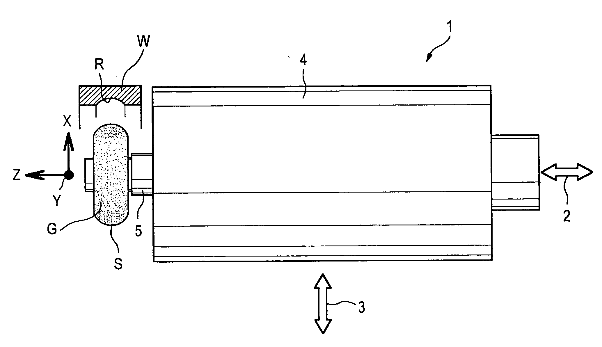
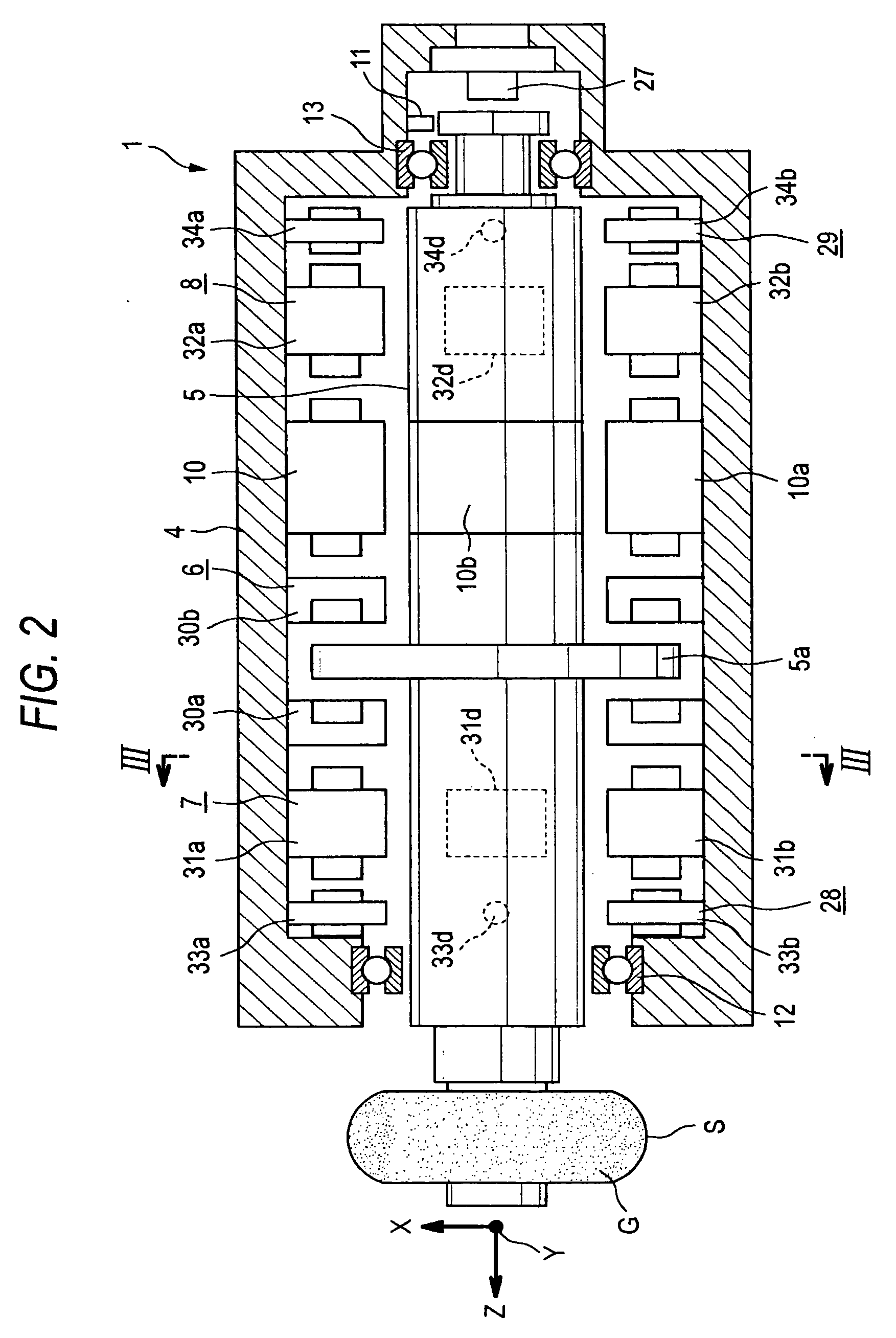
[0051]FIG. 1 is a side view illustrating a part of a magnetic bearing spindle unit that is a primary part of a grinding apparatus according to the invention. FIG. 2 is an enlarged cross-sectional view of the magnetic bearing spindle unit. FIG. 3 is a cross-sectional view taken along line III-III shown in FIG. 2. FIG. 4 is a block diagram illustrating a primary part of the electrical configuration of the spindle unit.

[0052]In the following description, it is assumed that an up-down direction as viewed in FIGS. 1 and 2 corresponds to an “up-down direction” of the grinding apparatus, that the left side as viewed in FIGS. 1 and 2 corresponds to a front side thereof, that the right side as viewed in FIGS. 1 and 2 corresponds to a rear side thereof, and that the left side and the right side, which are viewed from the rear side to the front side, correspond to the left side and the ri...


PUM

PropertyMeasurementUnit
stiffnessaaaaaaaaaa
axial displacementaaaaaaaaaa
shapeaaaaaaaaaa

Abstract

A grinding wheel having a convex grinding surface is attached to a wheel spindle that is contactlessly supported by a casing through a controlled type axial magnetic bearing and controlled type radial magnetic bearings and that is rotated by an electric motor. A groove of a workpiece is ground by causing relative displacement of the casing. After the axial positioning of the casing is performed, the casing is radially displaced. Then, the groove is ground. The stiffness value of the axial magnetic bearing 6 is set to be lower than a normal value before the casing is radially displaced. After it is detected that the grinding surface of the grinding wheel touches the entire groove of the workpiece and that the grinding of the entire surface of the workpiece is started, the stiffness value is set back to the normal value.

Description

BACKGROUND OF THE INVENTION[0001]The present invention relates to a grinding apparatus for grinding a groove in a cylindrical peripheral surface of a workpiece with a grinding wheel in which a convex grinding surface is formed on the outer peripheral surface.[0002]Internal cylindrical grinding machines are known as grinding apparatuses for performing finish grinding on raceway grooves formed in inner peripheral surfaces of outer rings of ball bearings.[0003]Conventional internal cylindrical grinding machines have used contact type rolling bearings as bearings for rotationally supporting a wheel spindle, on which a grinding wheel is mounted, on a casing of a spindle apparatus (see, e.g., JP-A-2001-159421 and JP-A-57-27660).[0004]As described above, the conventional internal cylindrical grinding machine for performing finish grinding on a groove formed on the inner peripheral surface of the outer ring of the ball bearing uses the rolling bearing for rotationally supporting a wheel spi...

Claims


Application Information

Patent Timeline
Patent Type & Authority Applications(United States)
IPC IPC(8): B24B5/00B24B5/10B24B41/04F16C32/04
CPCB24B41/044F16C33/64F16C32/0444F16C2322/39
Inventor KUBO, ATSUSHI
Owner JTEKT CORP
Why Eureka
Try Eureka