Method for installing a water well pump

Inactive Publication Date: 2005-02-24
UHLENKOTT WILLIAM
View PDF78 Cites 1 Cited by
  • Summary
  • Abstract
  • Description
  • Claims
  • Application Information

AI Technical Summary

Problems solved by technology

Second, removing a terminal portion of the wires from the conduit portion by way of the slot and severing the corresponding terminal portion of the conduit portion.

Method used


Image

  • Method for installing a water well pump
  • Method for installing a water well pump
  • Method for installing a water well pump

Examples


Embodiment Construction

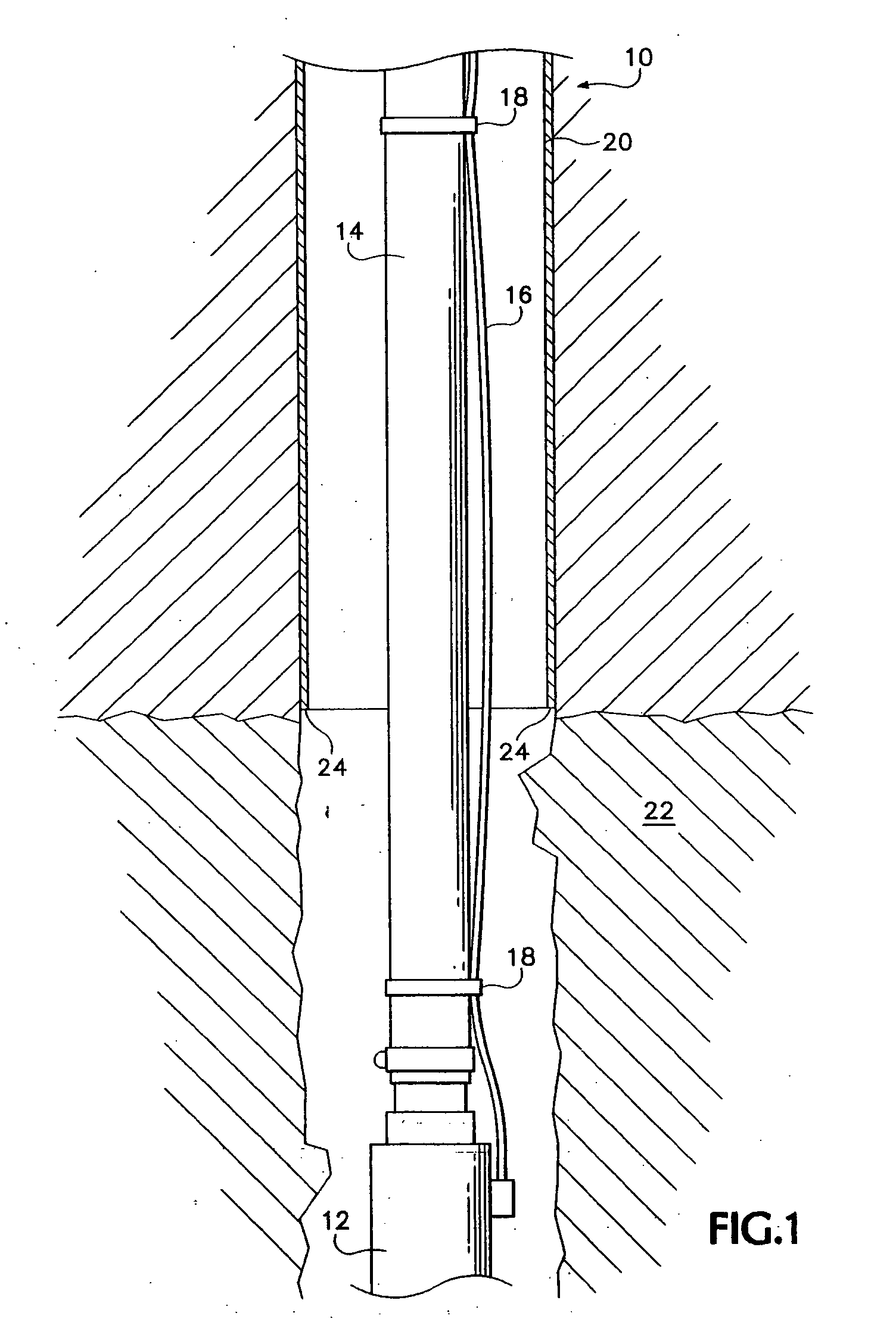
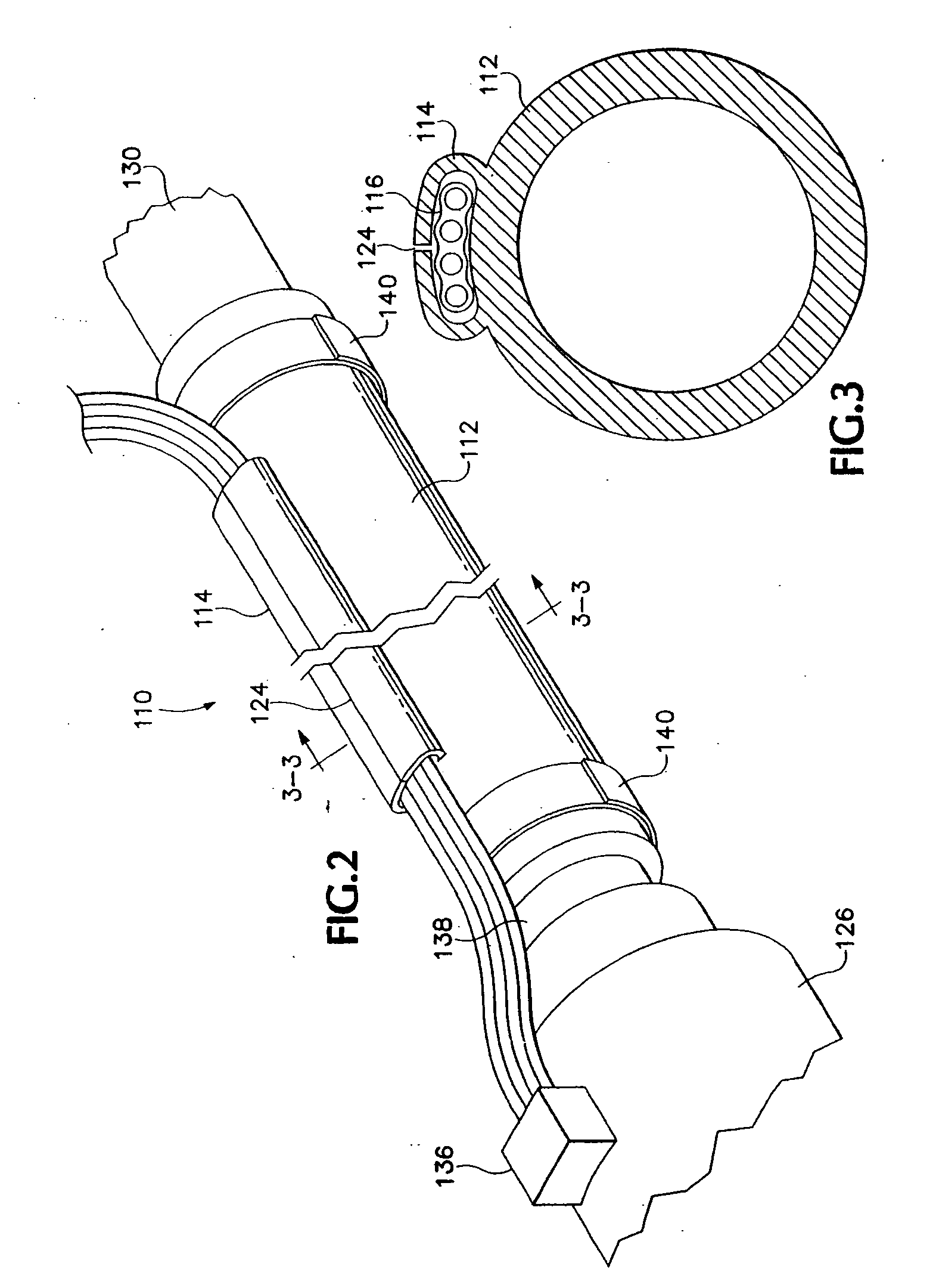
[0018] Referring to FIGS. 2 and 3, a preferred embodiment of the present invention is a hose and wire combination 110 preferably made of PVC or other flexible polymer. A hose portion 112 preferably has a one inch inner diameter and a one and three quarter inch outer diameter. It is to be understood that the hose and wire can be any size. A conduit portion 114 extends along the length of the hose portion 112 and accommodates a set of four individually insulated wires 116. A slot 124 extends the length of the conduit portion 114.

[0019] The hose and wire combination 110 is to be provided in a long length wrapped about a spool, to well pump installers. The installation would begin by pulling the ends of wires 116 through the slot 124 and snipping away the now empty end of conduit portion 114 so that it does not obstruct the attachment process. It may be necessary to cut back hose portion 112 so that wires 116 extend a sufficient length beyond hose portion 112 to permit connection. Then...


PUM


Abstract

A hose and wire combination adapted to provide water and electrical connections to a water well pump includes a hose adapted to bear water, a resilient-material conduit affixed to and extending longitudinally along the exterior of the hose and having a longitudinally extending slot and a set of wires extending longitudinally within the conduit and being electrically insulated from one another. A method of installing a pump comprises the steps of providing a hose and wire combination, removing a terminal portion of the wires from the conduit portion by way of the slot and severing the corresponding terminal portion of the conduit portion. Next, electrically connecting the set of at least four wires to the electrical terminals of the pump. Additionally, operatively connecting the hose to the water discharge spout of the pump. And finally, lowering the pump connected to the hose and wire combination into the well, thereby permitting the resilient material conduit to protect the wires during the lowering and afterwards during the operation of the pump.

Description

[0001] This application is a Continuation of U.S. patent application Ser. No. 10 / 412,792, filed Apr. 11, 2003; which is a Continuation of U.S. Pat. No. 6,668,934; which is a Continuation of U.S. Pat. No. 6,513,597; which is a Continuation of U.S. Pat. No. 6,302,213; which is a Continuation of U.S. Pat. No. 6,135,209.BACKGROUND OF THE INVENTION [0002] Referring to FIG. 1, after drilling a water well 10, an electric pump 12, which is connected to a hose 14 and an electric power cord 16, must be installed in the well for pumping water through the hose 14 to the surface. The power cord typically includes four wires, three for supplying single phase 220-volt power and a fourth to apply a ground for the pump 12. The power cord is typically spot bound to the hose 14 or pipe (with binding locations 18 separated by twenty feet of hose length or less) with tape or clamps as the pump 12, hose 14 and cord 16 are being lowered into the well. [0003] Unfortunately, this method leaves quite a bit t...

Claims


Application Information

Patent Timeline
Patent Type & Authority Applications(United States)
IPC IPC(8): E21B17/02E21B43/12
CPCE21B17/025E21B43/128E21B17/026
Inventor UHLENKOTT, WILLIAM
Owner UHLENKOTT WILLIAM
Why Eureka
Try Eureka