This helps you quickly interpret patents by identifying the three key elements:
Problems solved by technology
Method used
Benefits of technology
Benefits of technology
[0004] It would be desirable to provide an H-tap compression connector having increased mechanical strength.
[0007] It would also be desirable to provide an H-tap compression connector that facilitates one person installation.
Problems solved by technology
However, none of these prior art compression connectors have a transversely-oriented slot extending between a first pair of slots on one side of the compression connector and a second pair of slots on the other side of the compression connector.
Moreover, none of these prior art compression connectors have a longitudinally-oriented hole extending through the center of the compression connector.
Method used
Image
Click on the blue label to locate the original text in one second.
Reading with bidirectional positioning of images and text.
Examples
first embodiment
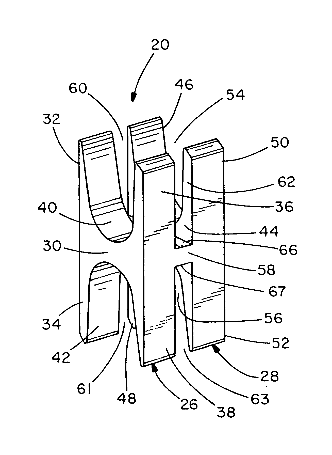
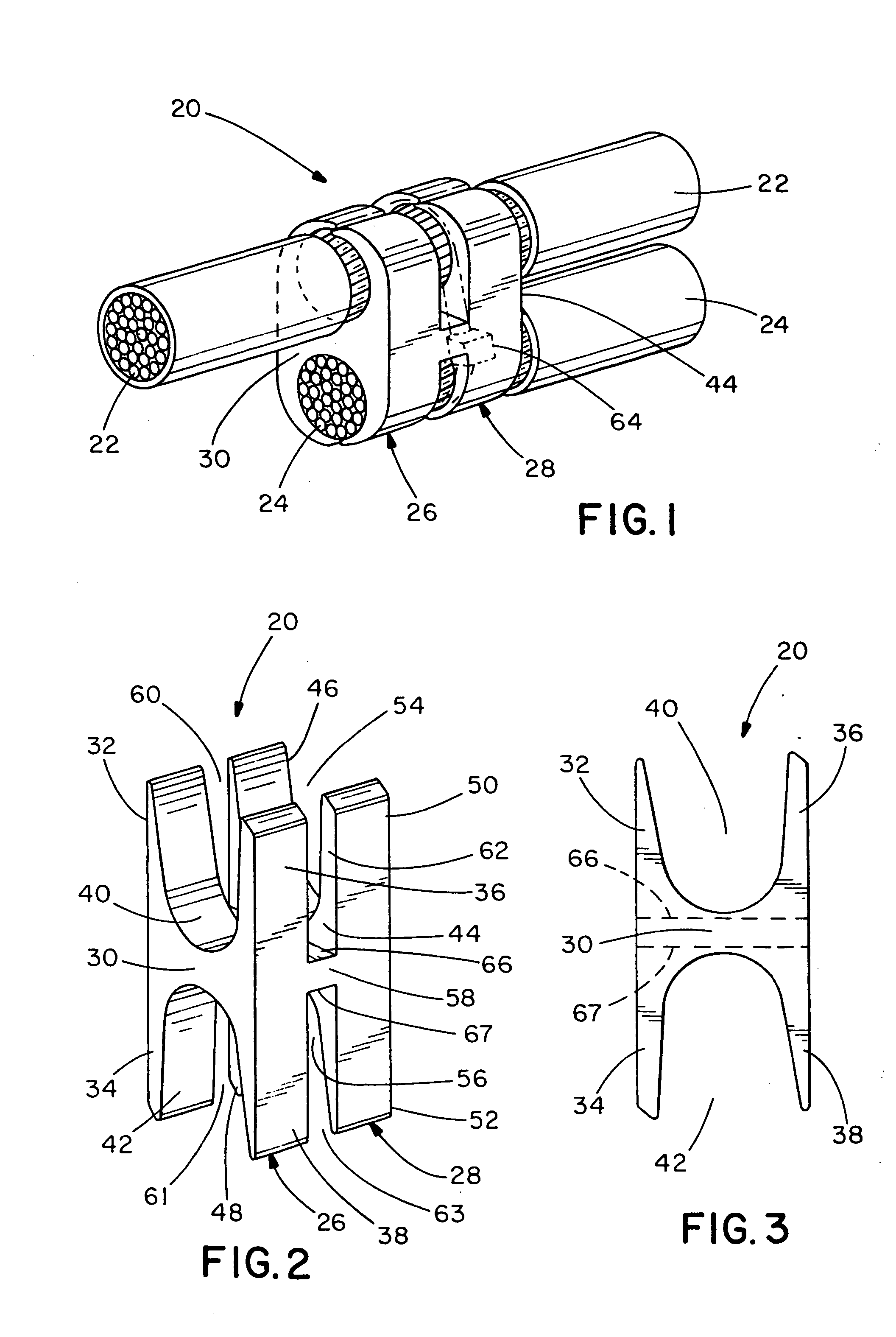
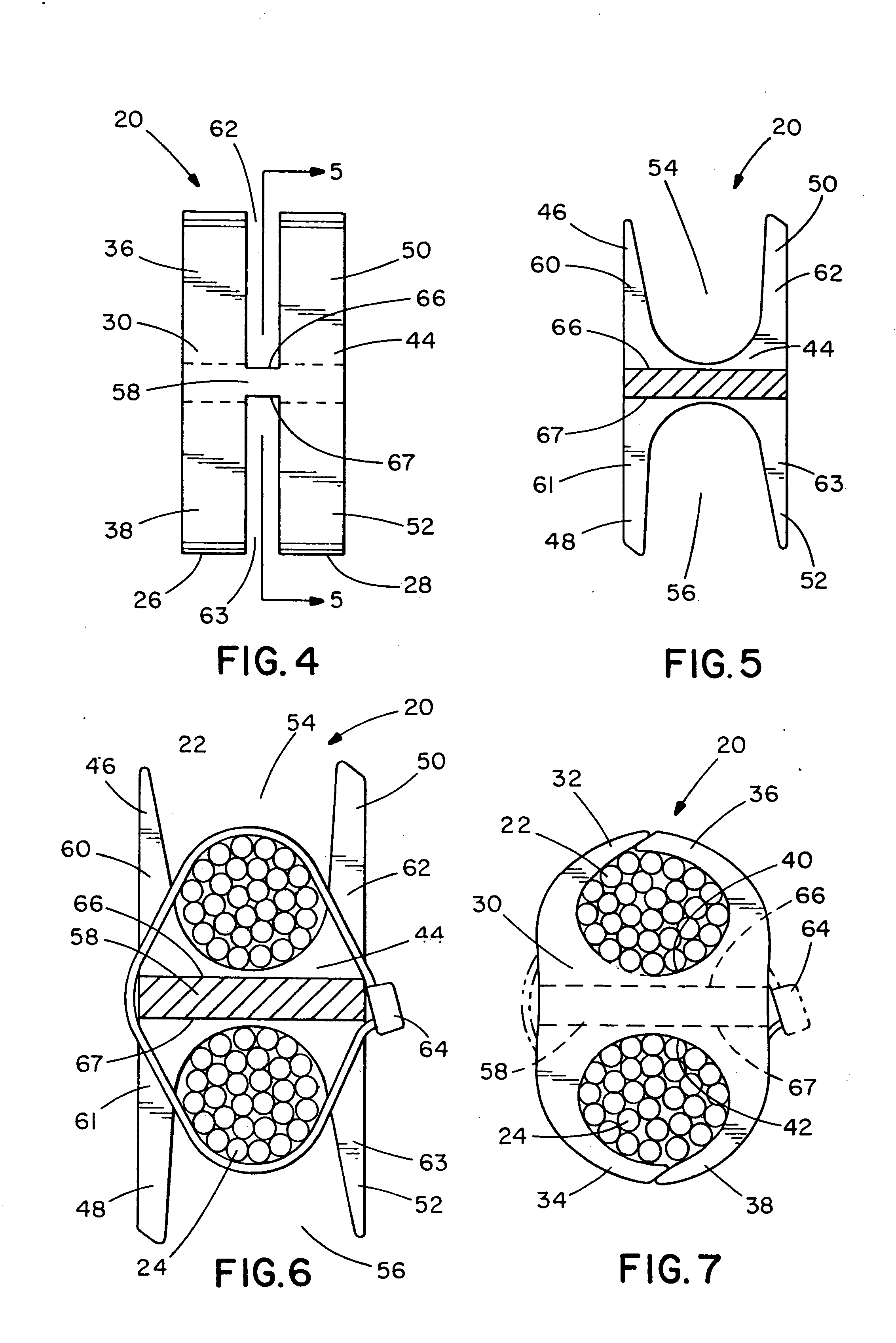
[0034] the present invention is illustrated in FIGS. 1-7. FIG. 1 shows an H-tap compression connector 20 secured around wires, such as run wires 22 and tap wires 24, after crimping. Preferably, compression connector 20 is a one-piece member made of electrically conductive material, such as copper. However, it is likewise contemplated that compression connector 20 may be made of any suitable materials or elements.
[0035] As shown in FIGS. 2-5, compression connector 20 has a first section 26 and a second section 28. First section 26 includes a first body portion 30 having four leg portions 32, 34, 36, 38 extending therefrom to form conductor receiving channels 40, 42 in which run wires 22 and tap wires 24 can be placed. Second section 28 is identical to first section 26. Thus, second section 28 includes a second body portion 44 having four leg portions 46, 48, 50, 52 extending therefrom to form conductor receiving channels 54, 56 in which run wires 22 and tap wires 24 can be placed. As...
second embodiment
[0038] the present invention is illustrated in FIGS. 8-10. As shown in FIG. 8, an H-tap compression connector 120 is substantially the same as compression connector 20 illustrated in FIGS. 1-7, except compression connector 120 has curved leg portions and is designed to accommodate smaller wires than compression connector 20. However, compression connector 120 functions similarly to compression connector 20.
third embodiment
[0039] the present invention is illustrated in FIGS. 11-13. As shown in FIG. 11, an H-tap compression connector 220 is substantially the same as compression connector 20 illustrated in FIGS. 1-7, except compression connector 220 has curved leg portions and is designed to accommodate smaller wires than compression connector 20. However, compression connector 220 functions similarly to compression connector 20 illustrated in FIGS. 1-7.
PUM
Abstract
A compression connector for securing wires therein is disclosed. The compression connector comprises a first body portion connected to a second body portion, each of the first and second body portions having two pairs of leg portions extending therefrom to form two conductor receiving channels, respectively. The compression connector also has a first pair of slots and a second pair of slots for receiving a cable tie to secure wires therein before crimping. At least one transversely-oriented slot extends between the first pair of slots and the second pair of slots. A method for securing wires within a compression connector is also disclosed.
Description
CROSS-REFERENCE TO RELATED APPLICATIONS [0001] This application claims priority to U.S. Provisional Application Ser. No. 60 / 413,768, filed on Sep. 26, 2002, and No. 60 / 491,113, filed on Jul. 30, 2003, the entireties of which are hereby incorporated by reference.BACKGROUND OF THE INVENTION [0002] The present invention is directed to an H-tap compression connector and, more particularly, to an H-tap compression connector with an easy installation feature and a longitudinally-oriented hole therethrough. [0003] Examples of H-tap compression connectors can be found in the following U.S. Pat. Nos. 2,307,216; 3,183,025; 3,235,654; 3,354,517; 5,162,615; 5,396,033; 5,552,564; 5,635,676; and 6,525,270. However, none of these prior art compression connectors have a transversely-oriented slot extending between a first pair of slots on one side of the compression connector and a second pair of slots on the other side of the compression connector. Moreover, none of these prior art compression con...
Claims
Application Information
Patent Timeline
Application Date:The date an application was filed.
Publication Date:The date a patent or application was officially published.
First Publication Date:The earliest publication date of a patent with the same application number.
Issue Date:Publication date of the patent grant document.
PCT Entry Date:The Entry date of PCT National Phase.
Estimated Expiry Date:The statutory expiry date of a patent right according to the Patent Law, and it is the longest term of protection that the patent right can achieve without the termination of the patent right due to other reasons(Term extension factor has been taken into account ).
Invalid Date:Actual expiry date is based on effective date or publication date of legal transaction data of invalid patent.

