Treadmill motor

A technology for treadmills and motors, applied in the direction of electromechanical devices, electrical components, electric components, etc., can solve the problems of small air flow, large motor vibration and noise, and poor vibration isolation effect, so as to reduce leakage current and improve insulation Improved performance and cooling effect

Active Publication Date: 2015-04-15
宁波长城电机有限公司
View PDF7 Cites 0 Cited by
  • Summary
  • Abstract
  • Description
  • Claims
  • Application Information

AI Technical Summary

Problems solved by technology

Most of the end covers of the prior art motors are closed, and although a small part has ventilation holes, these ventilation holes cannot form a good air duct, so that the heat on the windings cannot be well dissipated. take away, and the air flow that can be driven by the rotor of the prior art is small when it rotates, so that the winding can not be well radiated heat, resulting in poor heat dissipation effect of the whole motor; and the motor of the prior art is combined with the treadmill to work The vibration and noise are relatively large, the reason is that the motor and the treadmill will produce a resonance phenomenon, and the existing technology is used to overcome this resonance phenomenon, mainly by setting an ordinary rubber pad between the motor and the treadmill floor, and then passing The bolts are fixed, but the motor is still tightly connected to the bottom plate of the treadmill by bolts in this way. The vibration isolation effect between the motor and the bottom plate of the treadmill is poor, and resonance phenomenon will still occur. It is open, so the magnetic field on the surface of the rotor is not very smooth, resulting in greater vibration and noise when the motor is working

Method used


Image

  • Treadmill motor
  • Treadmill motor
  • Treadmill motor

Examples


Embodiment Construction

[0030] The present invention will be further described below in conjunction with the accompanying drawings and specific embodiments, but the present invention is not limited to the following specific embodiments.

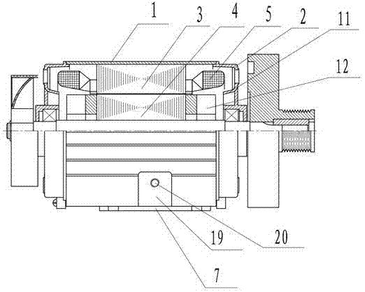
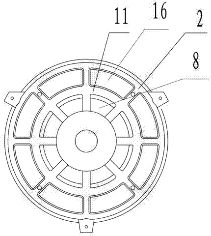
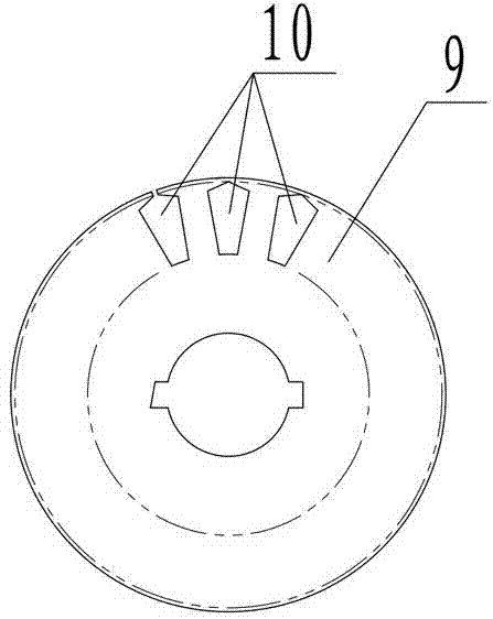
[0031] As shown in the figure: a treadmill motor, including a housing 1, end caps 2 arranged at both ends of the housing 1, a stator 3 and a rotor 4 arranged in the housing 1, and a winding 5, on the housing 1 A motor foot 7 is provided, and the motor foot 7 is fixedly connected to the treadmill base plate 6 by bolts 15. The rotor 4 includes a plurality of rotor punches 9, and a plurality of rotors are arranged in the multi-piece rotor punch 9. slots 10, and the rotor slots 10 are evenly distributed along the circumference of the rotor punch 9, the inner ring of the end cover 2 is provided with a plurality of air inlets 8, and the outer ring of the end cover 2 is provided with a plurality of air outlets 16, so The air inlet 8 corresponds to the air outlet 16 one by ...


PUM


Abstract

The invention relates to the technical field of motors, particularly to a treadmill motor. The motor comprises a case (1), end covers (2), a stator (3), a rotor (4) and a winding (5), wherein the end covers (2) are arranged at two ends of the case (1), the stator (3) and the rotor (4) are arranged in the case (1), the rotor (4) comprises a plurality of rotor laminations (9), a plurality of air inlets (8) are arranged on inner rings of the end covers (2), a plurality of air outlets (16) are arranged on outer rings of the end covers (2), the plurality of air inlets (8) are in one to one correspondence to the plurality of air outlets (16), an air shielding block (11) is arranged between the air inlets (8) and the air outlets (16), and the thickness of the air shielding block (11) is larger than the distance between the end of the winding (5) and the outer walls of the end covers (2). The treadmill motor is good in cooling effect.

Description

technical field [0001] The invention relates to the technical field of motors, in particular to a treadmill motor. Background technique [0002] Treadmill is a common equipment for home and gym, and it is the simplest type of home fitness equipment today, and it is the best choice for home fitness equipment. The treadmill motor (hereinafter referred to as the motor) is the power source of the treadmill. Because the motor is used in a relatively sealed space, the heat dissipation of the motor is very important. Most of the end covers of the prior art motors are closed, and although a small part has ventilation holes, these ventilation holes cannot form a good air duct, so that the heat on the windings cannot be well dissipated. take away, and the air flow that can be driven by the rotor of the prior art is small when it rotates, so that the winding can not be well radiated heat, resulting in poor heat dissipation effect of the whole motor; and the motor of the prior art is...

Claims


Application Information

Patent Timeline
Patent Type & Authority Patents(China)
IPC IPC(8): H02K9/02H02K9/06H02K5/24H02K3/34H02K5/26
Inventor 朱方正朱坚枫
Owner 宁波长城电机有限公司
Why Eureka
Try Eureka