Motorized bicycle drive system using a standard freewheel and left-crank drive

a technology of freewheel drive and motorized bicycle, which is applied in the direction of bicycles, transportation and packaging, russian swings, etc., can solve the problems of unnecessarily complex and expensive systems, requiring a significant monetary expenditure, and the vast majority of ingenious mechanisms are worthless, so as to reduce the complexity of the driv

Inactive Publication Date: 2005-02-24
FORDERHASE PAUL F
View PDF7 Cites 37 Cited by
  • Summary
  • Abstract
  • Description
  • Claims
  • Application Information

AI Technical Summary

Benefits of technology

[0013] It is desirable to reduce drive complexity by only requiring one freewheel. By positively driving the crank axle, the current invention reduces the number of required freewheels to one, thus placing the system within the monetary reach of almost anyone who can afford a bicycle.

Problems solved by technology

The vast majority of these ingenious mechanisms are worthless if one is contemplating a modification of an existing machine.
The modifications range from a radical redesign of the frame and transmission to a large and ungainly addition to the front or rear wheel.
Both systems, however, are unnecessarily complex and expensive.
This requirement not only requires a significant monetary expenditure on the part of the aspiring motorist, but also raises the possibility that extensive adjustment and debugging will be required to get the system to function properly, since it is well known that bicycle derailleur systems must be tuned and adjusted extensively.
Any disturbance or replacement of part of the bicycle transmission is therefore undesirable.
Roller clutches are notoriously sensitive to the surface finish and cleanliness of the shaft against which they operate.
Both Murphy and Rizzeto fail to mention how to accommodate the various control cable positions which are typically placed along the down tube of a bicycle having rear, and optionally, front derailleur or other gear change mechanisms.
The often sensitive and finely tuned front transmission system of the bicycle is undisturbed.

Method used


Image

  • Motorized bicycle drive system using a standard freewheel and left-crank drive
  • Motorized bicycle drive system using a standard freewheel and left-crank drive
  • Motorized bicycle drive system using a standard freewheel and left-crank drive

Examples


Embodiment Construction

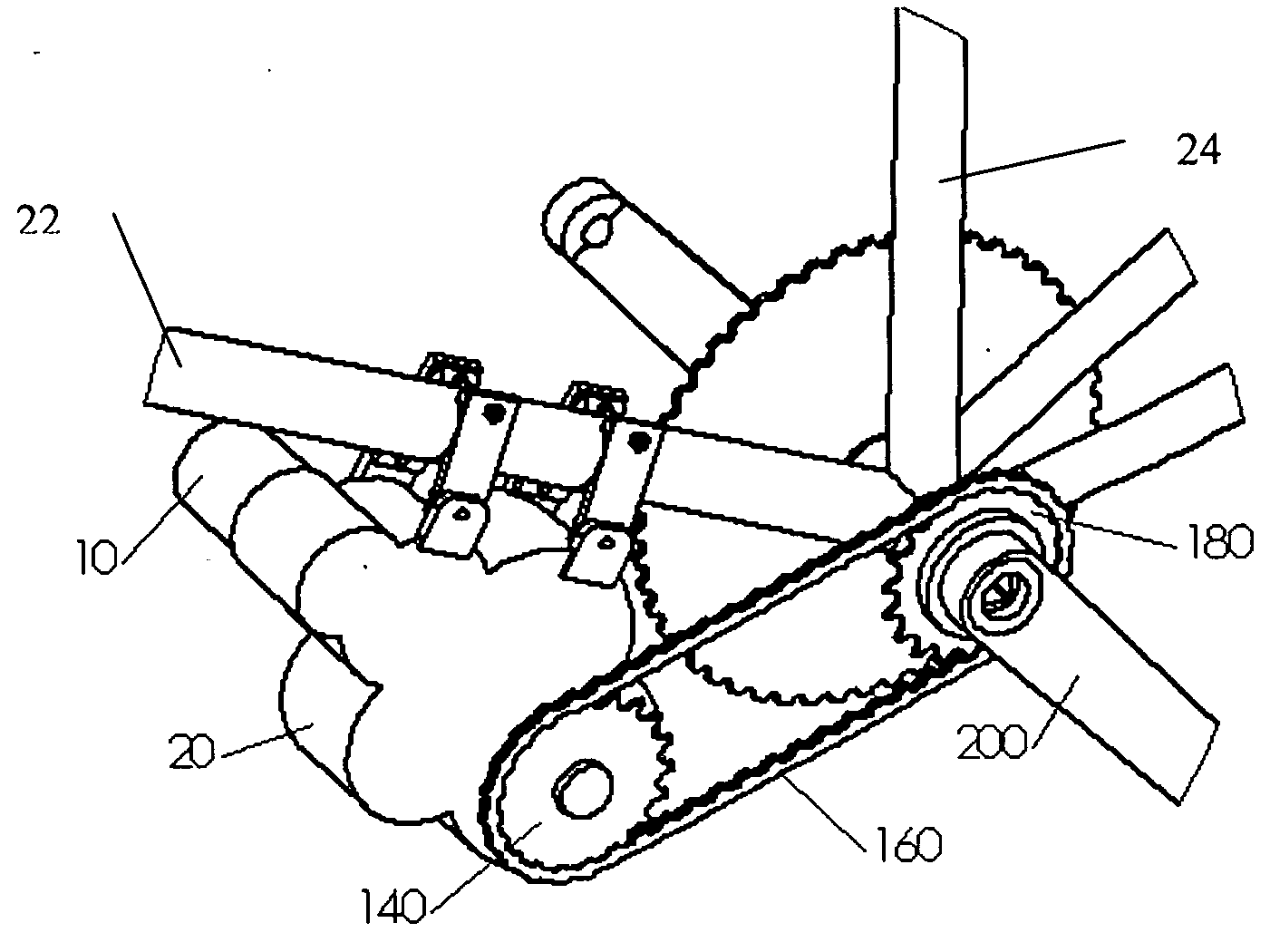
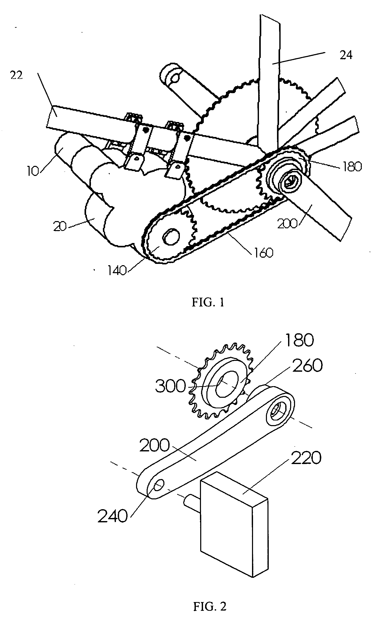
[0026] An embodiment is shown in FIG. 1 and FIG. 2. Motor 10, is connected through a suitable reduction means such as a gear box housing 20 that provides a reduction in velocity and increase in torque to sprocket 140. Power is then transmitted through drive chain 160 to freewheel 180 threaded onto a crank 200. Crank 200 is threaded at hole 240 to accept a standard left pedal 220. This crank has a threaded boss 260 extending inwardly toward the center of the bike when mounted, the thread being sized to fit the female thread 300 of a single-speed freewheel 260. In this embodiment, the axis of the threaded boss 260 features the four-sided, tapered socket normally used to fasten “cotterless” style cranks to the crank axle.

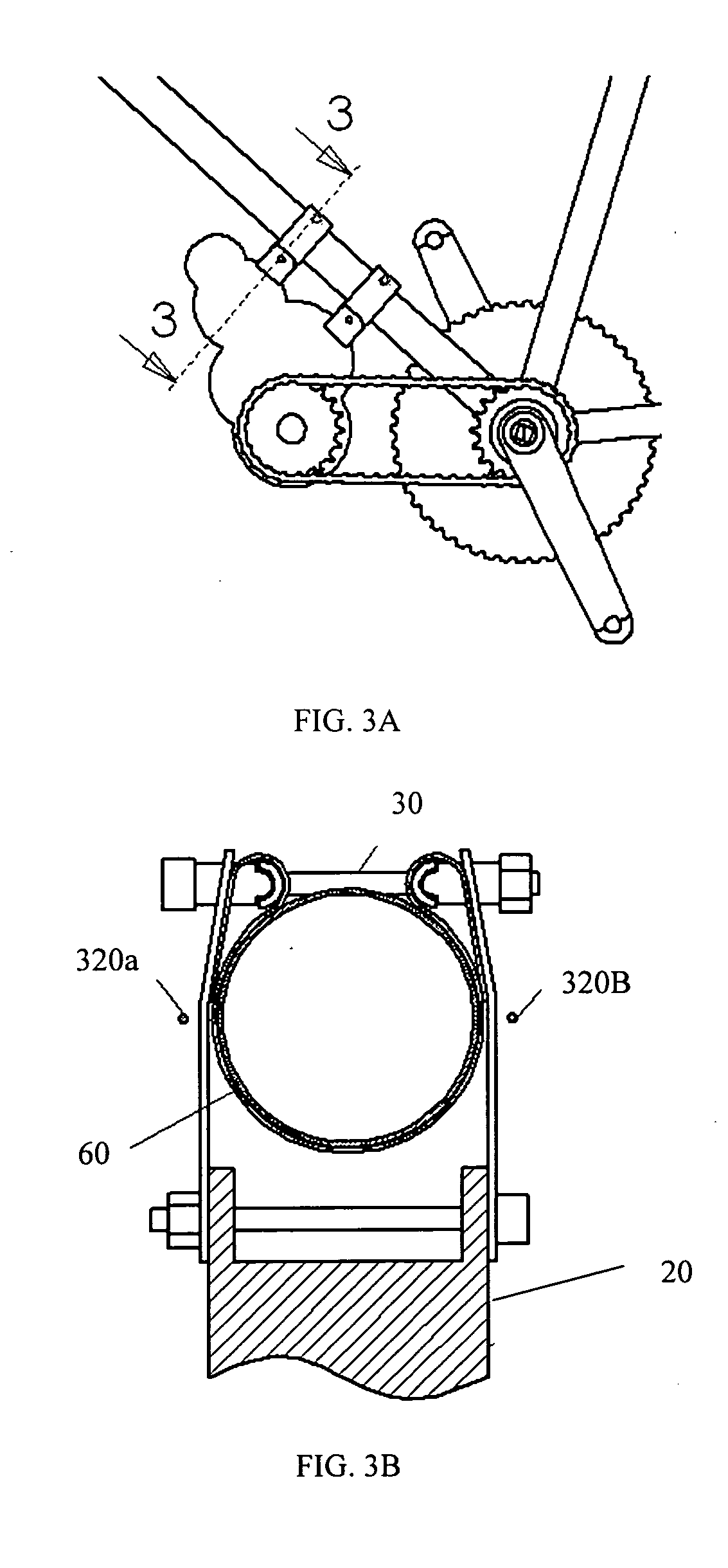
[0027] The gearbox is fitted to the bicycle frame 24 either below or above the down tube 2l with an attachment means such as constrictive clamps such as the type shown in FIG. 3a-3d. In this example, the clamps are attached by brackets 120 to the gearbox at two points...


PUM


Abstract

An auxiliary power system for a bicycle having a motor (10) attached to the bicycle flame (22) by thin clamps (30), which can be arranged in a variety of positions to avoid disturbing the control cables. Power is delivered on demand via a sprocket driving a single freewheel (180) attached to a modified left crank (200). The gearbox (20) may be attached to the frame by means of a quick-release system. A bushing (600), (700), (820) may be used instead of a modified as a means of mounting the freewheel to the crank axle. (720), (610), (850b). To prevent accidental simultaneous braking and triggering, triggering the system is accomplished by placing the trigger switch (430) so that the rider's fingers must disengage the brake in order to engage the motor. Accidental triggering may be prevented by placing a trigger switch on each handle and wiring them in series so that both switches must be engaged to obtain power.

Description

RELATED APPLICATIONS [0001] This application is related to U.S. Provisional Patent Application No. 60 / 471,785 filed May 20, 2003, and claims the benefit of that Provisional Application.FEDERALLY SPONSORED RESEARCH [0002] Not Applicable SEQUENCE LISTING OR PROGRAM [0003] Not Applicable BACKGROUND: FIELD OF INVENTION [0004] This invention relates to the field of motorized bicycle power systems, more specifically to electric systems driving the cranks of that bicycle. BACKGROUND: DISCUSSION OF THE PRIOR ART [0005] There is an extensive body of patents that require extensive modification of the frame of the bicycle in order to assist the rider or to fully power the vehicle. The vast majority of these ingenious mechanisms are worthless if one is contemplating a modification of an existing machine. The modifications range from a radical redesign of the frame and transmission to a large and ungainly addition to the front or rear wheel. A few of the most notable innovations in the field of ...

Claims


Application Information

Patent Timeline
Patent Type & Authority Applications(United States)
IPC IPC(8): B62M6/55B62M1/36
CPCB62M6/55B62M1/36
Inventor FORDERHASE, PAUL F.
Owner FORDERHASE PAUL F
Why Eureka
Try Eureka