Plate voltage generation circuit capable controlling dead band

a voltage generation circuit and dead band technology, applied in logic circuits, pulse techniques, instruments, etc., can solve problems such as voltage level instability, current interference with stabilization, and through current becoming a problem

Inactive Publication Date: 2005-02-24
LONGITUDE SEMICON S A R L
View PDF4 Cites 10 Cited by
  • Summary
  • Abstract
  • Description
  • Claims
  • Application Information

AI Technical Summary

Benefits of technology

This patent describes a new circuit design for producing plates of electricity called a plate voltage generation circuit. It has several key features: a differential section where different voltages are applied, a push-pull output section that generates the actual voltage, and a dead-band control section that adjusts how sensitive the output voltage is to changes in input signals. These features allow for better regulation and stability during use. Additionally, there may be multiple versions of this circuit designed specifically for certain applications such as powering electronic devices.

Problems solved by technology

The technical problem addressed in this patent text is to control the through current in a plate voltage generation circuit used in a push-pull output circuit without affecting the stability of the voltage level. The conventional technique of setting a dead band in the output voltage to suppress the through current results in a decrease in the response speed of the circuit. This invention proposes a new technique for controlling the width of the dead band without changing the power supply voltage or the resistances of the resistors in the reference potential generation circuit. The new technique allows for a smaller through current in the output buffer circuit without affecting the stability of the voltage level.

Method used


Image

  • Plate voltage generation circuit capable controlling dead band
  • Plate voltage generation circuit capable controlling dead band
  • Plate voltage generation circuit capable controlling dead band

Examples


Embodiment Construction

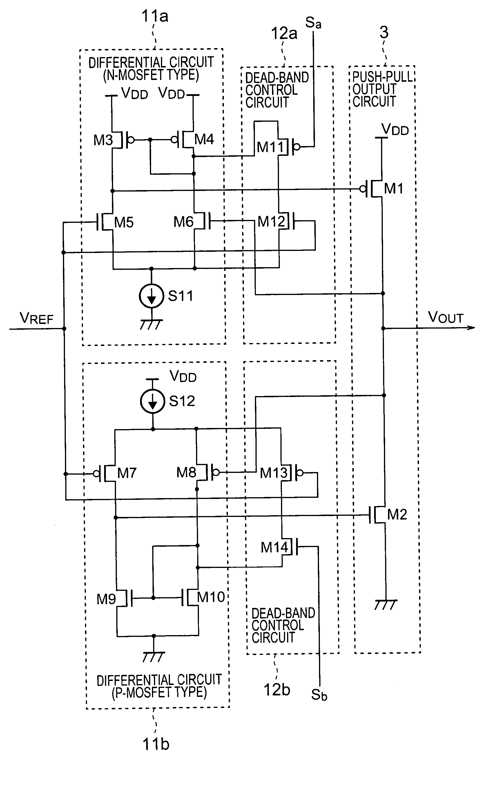
[0044] The outline of the present invention will be described with reference to FIG. 4. Referring to FIG. 4, a plate voltage generation circuit 1 receives a voltage, that is half an external power supply voltage VDD, as a reference voltage VREF and then generates a voltage around the reference voltage VREF as an output voltage VOUT. The plate voltage generation circuit 1 has a dead-band control circuit 2. The dead-band control circuit 2 receives first and second dead-band control signals Sa and Sb, which are used to externally control the width of a dead band. On the basis of the received dead-band control signals Sa and Sb, the dead-band control circuit 2 controls the width of the dead band in the output voltage VOUT. The dead-band control circuit 2 can be included in the plate voltage generation circuit or can be externally attached thereto.

[0045] According to the dead-band control signals Sa and Sb, the operation of the dead-band control circuit 2 is controlled, namely, the dead...


PUM


Abstract

A plate voltage generation circuit comprises: first and second differential circuits (11a, 11b) supplied with a reference voltage (VREF) and an output voltage (VOUT), respectively; a push-pull output circuit (3), connected to the first and second differential circuits, for generating the output voltage; and first and second dead-band control circuits, connected to the first and second differential circuits, respectively, for changing the width of a dead band of the output voltage in accordance with a high level or a low level of dead-band control signals (Sa, Sb) externally supplied.

Description


Claims


Application Information

Patent Timeline
Owner LONGITUDE SEMICON S A R L
Why Eureka
Try Eureka