Apparatus and method for increasing a slew rate of an operational amplifier

a technology of operational amplifier and slew rate, which is applied in the direction of dc-amplifiers with dc-coupled stages, differential amplifiers, and amplifiers with semiconductor devices/discharge tubes, etc. it can solve the problems of increasing the quiescent/operating current consumption, sacrificing the stability of the opamp, and increasing the slew rate. , to achieve the effect of increasing the slew rate of an operational amplifier, increasing the static curren

Inactive Publication Date: 2005-08-18
NOVATEK MICROELECTRONICS CORP
View PDF5 Cites 9 Cited by
  • Summary
  • Abstract
  • Description
  • Claims
  • Application Information

AI Technical Summary

Benefits of technology

[0012] Another object of the present invention is to provide an apparatus and method for increasing the slew rate of an operational amplifier, especially for driving a heavy loading
[0013] Still another object of the present invention is to provide an apparatus and method for increasing a slew rate of an operational amplifier without increasing the static current consumption.
[0014] Still another object of the present invention is to provide an apparatus and method for increasing a slew rate of an operational amplifier without changing the pole-zero of the operational amplifier. The apparatus and method for increasing a slew rate of an operational amplifier of the present invention use a monitoring control device controlled by the output stage to control the supplementary output device and the supplementary input device in order to increase a slew rate of an operational amplifier. Hence, the apparatus and method for increasing a slew rate of an operational amplifier of the present invention have the advantages of low quiescent / operating current, high slew rate, small chip size, and compact structure.
[0037] The present invention provides a method for increasing a slew rate of an operational amplifier, the operational amplifier including an input stage and an output stage, the input stage receiving an input signal, the operational amplifier amplifying the input signal, the output stage outputting an output signal via an output terminal, the output signal being the amplified input signal, the method comprising: using a gate driving voltage of the output stage to provide a supplementary output current to the output terminal and to provide a supplementary input current to the input stage in order to increase the slew rate of the operational amplifier.

Problems solved by technology

However, the former will increase the quiescent / operating current consumption; the latter will sacrifice the stability of the OPAMP.
Although those conventional methods can increase the slew rate, they also have some drawbacks such as increase of the chip size, increase of the current, and sacrifice of the stability.
Hence, the push-pull output stage requires a huge static current consumption.
I.e., it is very difficult to achieve low power consumption and a high slew rate at the same time.
Further, the circuit looks very simple, but practically is very complicated.
Hence, those considerations inevitably increase the size of the chip and the production cost.
The above limitations make the above structure more complicated and occupy a huge size.
Hence, although the conventional OPAMP 100 can provide an excellent driving ability and a simple structure, it occupies a huge size and increases the production cost.
In addition, the issue of cross distortion, the problems generated from the characteristics of the error amplifier, and the issue of the high power consumption have to be considered.

Method used


Image

  • Apparatus and method for increasing a slew rate of an operational amplifier
  • Apparatus and method for increasing a slew rate of an operational amplifier
  • Apparatus and method for increasing a slew rate of an operational amplifier

Examples


Embodiment Construction

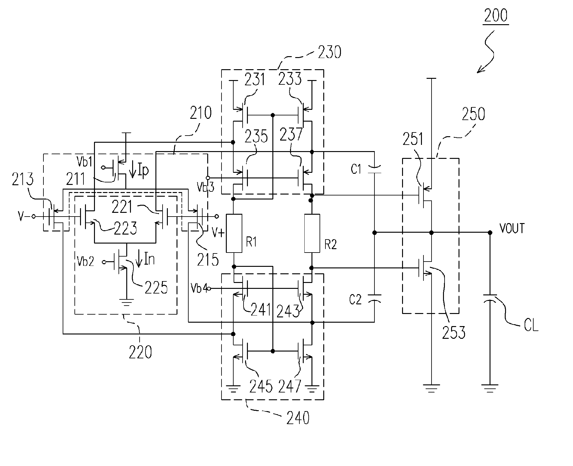
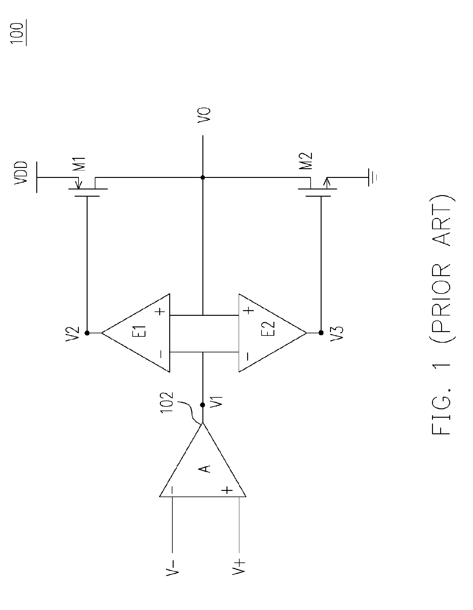
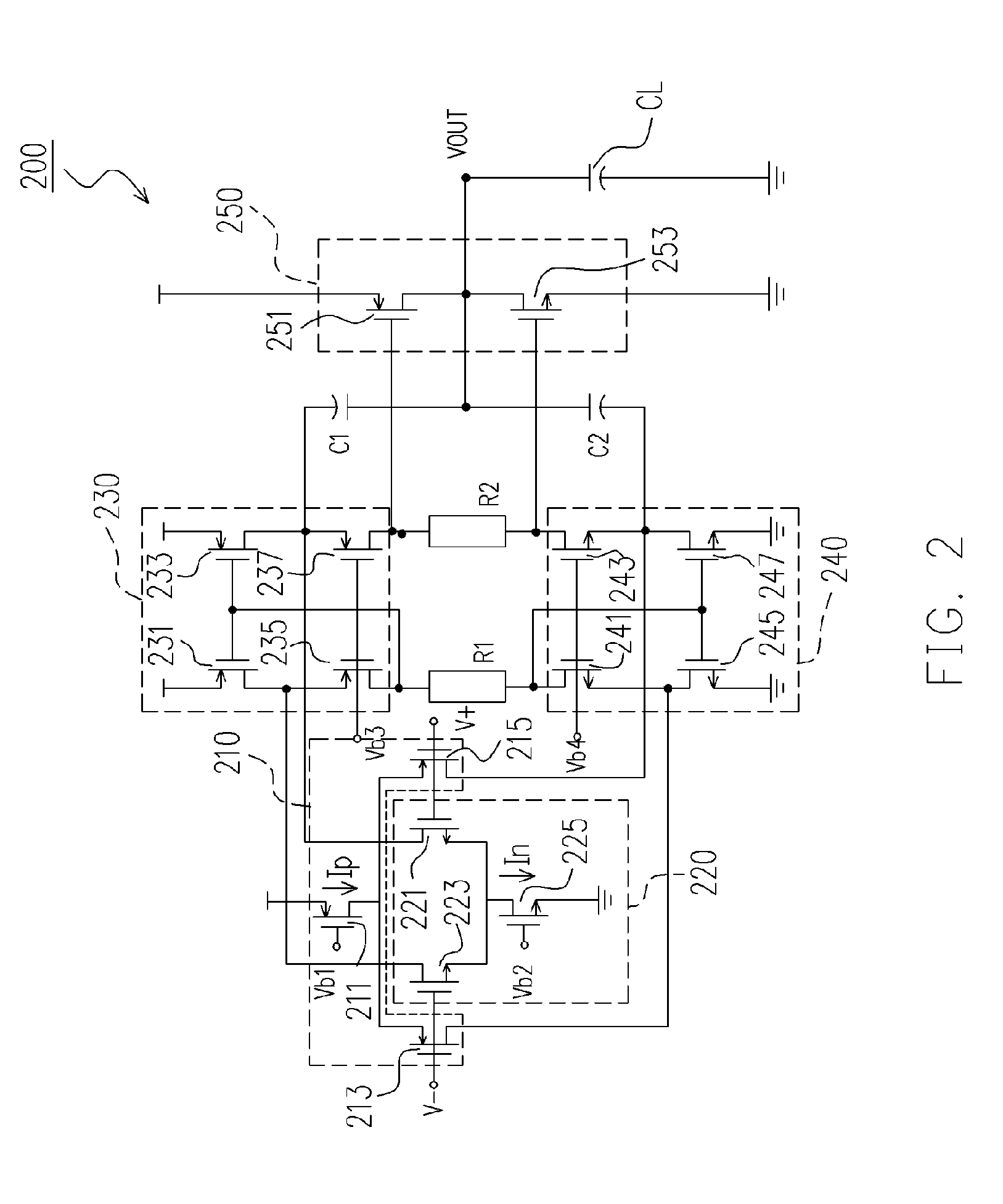
[0051] The present invention provides an apparatus for increasing a slew rate of an operational amplifier. It uses a monitoring control device controlled by the output stage to control the supplementary input / output device in order to increase the slew rate of an operational amplifier. It is different from the conventional operational amplifier with a high slew rate, which uses the error amplifier to monitor the voltage difference between the input terminal and the output terminal in order to control the output stage. The present invention uses a totally different concept to use the operational amplifier to drive a heavy capacitor loading (30 pF-600 pF) and has the advantages of low static current, high slew rate, small chip size and compact structure. Unlike the present invention, the conventional operational amplifier with a high slew rate does not provide low static current, small chip size and compact structure.

[0052] The apparatus for increasing a slew rate of an operational a...


PUM


Abstract

An apparatus and method for increasing a slew rate of an operational amplifier are provided. It only requires an operational amplifier, a monitoring control device, a push-pull output device, and a second input current source pair. It uses a monitoring control device controlled by the output stage to control the supplementary device and the second input current source pair in order to increase a slew rate of an operational amplifier. This operational amplifier also provides the rail-to-rail output function. In addition, because it does not require additional circuit to increase the slew rate, the chip size is smaller. With respect to the circuit structure, it is very simple and can be applied to the pre-existing operational amplifier without re-designing the operational amplifier and thus can keep the original characteristics of the operational amplifier.

Description

CROSS-REFERENCE TO RELATED APPLICATION [0001] This application claims the priority benefit of Taiwan application Serial No. 93103710 on Feb. 17, 2004. BACKGROUND OF THE INVENTION [0002] 1. Field of the Invention [0003] This invention generally relates to an apparatus and method for increasing a slew rate of an operational amplifier, and more particularly to an apparatus and method for increasing a slew rate of an operational amplifier by using a monitoring control device controlled by the output stage to control the supplementary output device and the supplementary input device in order to increase a slew rate of an operational amplifier. [0004] 2. Description of Related Art [0005] To acquire a higher slew rate of the operational amplifier (OPAMP), the conventional methods include increasing the current of the differential input pair or reducing the compensation capacitance. However, the former will increase the quiescent / operating current consumption; the latter will sacrifice the ...

Claims


Application Information

Patent Timeline
Patent Type & Authority Applications(United States)
IPC IPC(8): H03F3/00H03F3/30H03F3/45
CPCH03F3/3022H03F3/45192H03F2203/45028H03F2203/45632H03F2203/45366H03F2203/45631H03F2203/45248
Inventor SUNG, KUANG-FENG
Owner NOVATEK MICROELECTRONICS CORP
Why Eureka
Try Eureka