Data driver and organic light emitting display having the same

a data driver and light-emitting display technology, applied in the field of data drivers, can solve the problems of limiting the slew rate reduction, and achieve the effects of reducing power consumption, reducing the size of the data driver ic, and improving the slew rate of the output buffer

Active Publication Date: 2011-03-03
SAMSUNG DISPLAY CO LTD
View PDF4 Cites 30 Cited by
  • Summary
  • Abstract
  • Description
  • Claims
  • Application Information

AI Technical Summary

Benefits of technology

[0018]An embodiment of the present invention is directed toward a data driver and an organic light emitting display having the same. The data driver has a switch unit provided between output terminals of respective output buffers (that are provided in the data driver) and data lines corresponding thereto. Here, the switch unit is also coupled to a source for providing a middle voltage VM, VM′, and allows the output terminals of the output buffers to be coupled to receive the middle voltage VM, VM′ before data signals are output from the data driver by the operation of the switch unit, making it possible to improve the slew rate of the output buffer and to reduce power consumption.
[0027]With the embodiments as described above, the switch unit is provided between the output terminals of the respective output buffers provided in the data driver and the data lines corresponding thereto and is coupled to receive the middle voltage. As such, the output terminals of the output buffers can be coupled to receive the middle voltage before the data signals are output from the data driver by the operation of the switch unit. Thereby, the slew rate of the output buffer is improved, and the power consumption is reduced.
[0028]Moreover, because the slew rate is improved, it is possible to reduce the size of the data driver IC.

Problems solved by technology

However, in the related art, the slew rate of the output signal output from the data driver depends on the bias current IBP1 and IBN1 of the output buffer and the compensation capacitor C, which limit how much the slew rate can be reduced.

Method used


Image

  • Data driver and organic light emitting display having the same
  • Data driver and organic light emitting display having the same
  • Data driver and organic light emitting display having the same

Examples


Embodiment Construction

[0037]Hereinafter, certain exemplary embodiments according to the present invention will be described with reference to the accompanying drawings. Here, when a first element is described as being coupled to a second element, the first element may be not only directly coupled to the second element but may also be indirectly coupled to the second element via one or more third elements. Further, some of the elements that are not essential to the complete understanding of the invention are omitted for clarity. Also, like reference numerals refer to like elements throughout.

[0038]Hereinafter, exemplary embodiments of the present invention will be described in more detail with reference to the accompanying drawings.

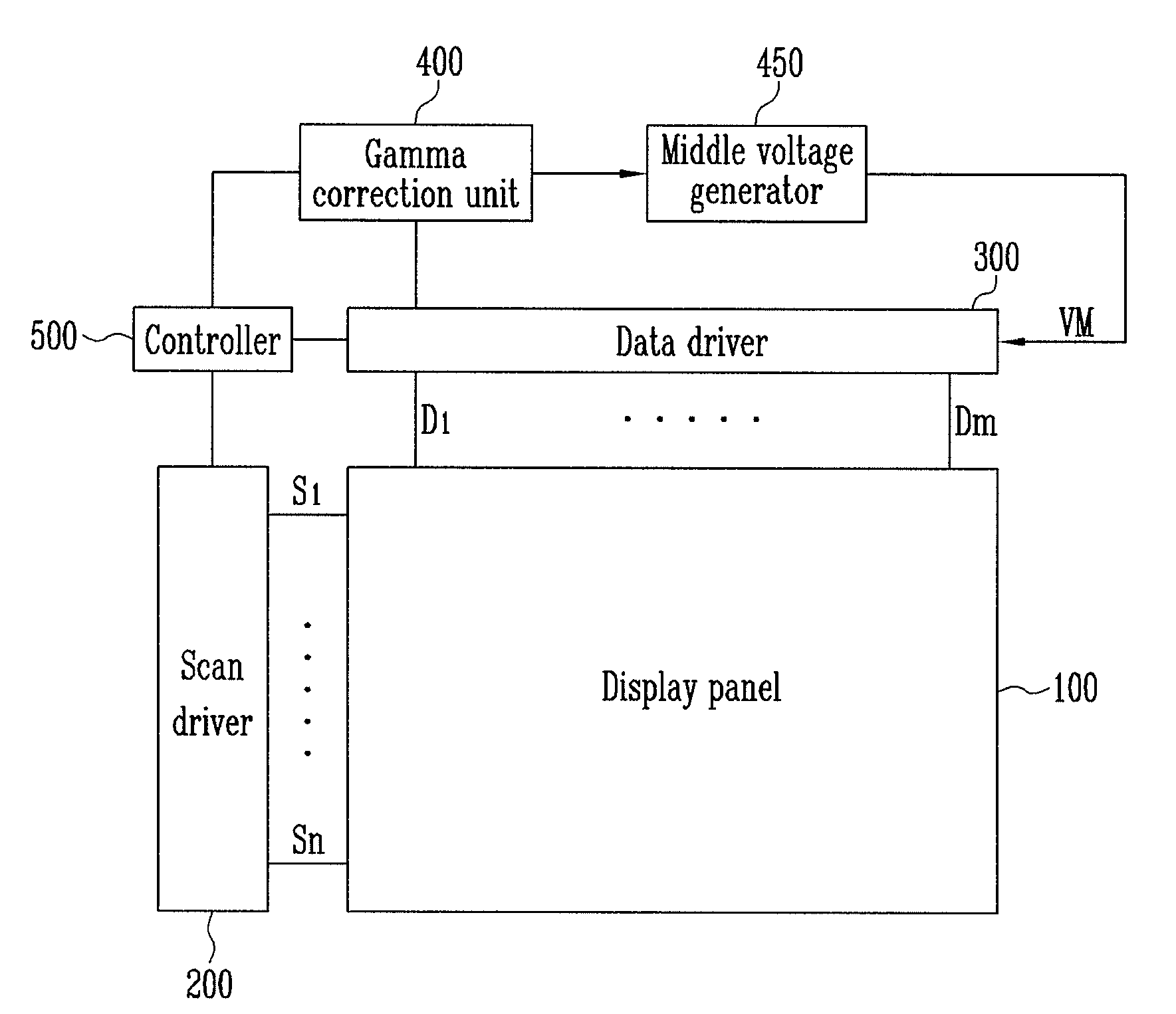
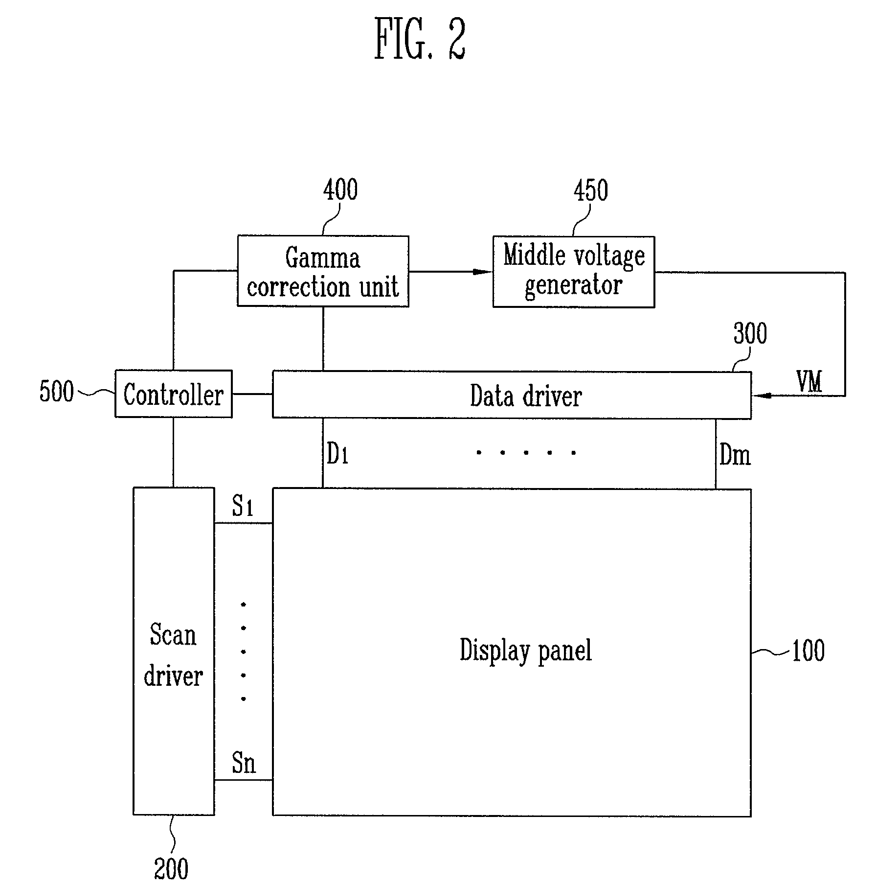
[0039]FIG. 2 is a perspective block diagram showing the constitution of an organic light emitting display according to an embodiment of the present invention.

[0040]Referring to FIG. 2, the organic light emitting display includes a display panel 100, a scan driver 200, a data dr...


PUM


Abstract

A data driver and an organic light emitting display having the same. The data driver has a switch unit provided between output terminals of respective output buffers that are provided in the data driver and data lines corresponding thereto. Here, the switch unit is also coupled to a source for providing a middle voltage, and allows the output terminals of the output buffers to be coupled to receive the middle voltage before data signals are output from the data driver by the operation of the switch unit, making it possible to improve the slew rate of the output buffer and to reduce power consumption, and an organic light emitting display having the same. The switch unit may includes a first switch coupled between the source for providing the middle voltage and the output terminals, and a second switch coupled between the output terminals and the respective data lines.

Description

CROSS-REFERENCE TO RELATED APPLICATION[0001]This application claims priority to and the benefit of Korean Patent Application No. 10-2009-0079791, filed on Aug. 27, 2009, in the Korean Intellectual Property Office, the entire content of which is incorporated herein by reference.BACKGROUND[0002]1. Field[0003]An embodiment of the present invention relates to a data driver, and more particularly, to a data driver that controls the slew rate of an output buffer provided in the data driver and an organic light emitting display having the same.[0004]2. Description of Related Art[0005]Recently, various flat panel displays that are light in weight and smaller in volume than that of an equivalent cathode ray tube, have been developed. Here, a flat panel display can be a liquid crystal display, a field emission display, a plasma display panel, a light emitting display, etc.[0006]A flat panel display typically includes a display panel, a scan driver, and a data driver. The scan driver outputs s...

Claims


Application Information

Patent Timeline
Patent Type & Authority Applications(United States)
IPC IPC(8): G09G5/10G09G5/00
CPCG09G3/20G09G3/3208G09G3/3291G09G2310/027G09G2360/16G09G2320/0252G09G2320/0673G09G2330/021G09G2330/028G09G2310/0291G09G3/30
Inventor PARK, JUNG-KOOK
Owner SAMSUNG DISPLAY CO LTD
Why Eureka
Try Eureka