
Novel structure transformer

A transformer and a new structure technology, applied in the field of transformers, can solve problems such as not easy water cooling or air cooling, increased manufacturing difficulty, small cross-sectional area, etc., and achieve good heat dissipation effect, simple maintenance, and simple high current output.

Active Publication Date: 2007-12-05
中山市华星电源科技有限公司
View PDF1 Cites 28 Cited by
  • Summary
  • Abstract
  • Description
  • Claims
  • Application Information

AI Technical Summary

Problems solved by technology

However, the processing of the above-mentioned patents must adopt welding technology, which requires high welding technology, and the insulation is difficult to handle, which increases the difficulty of manufacturing; while the secondary side adopts the shell type, the cross-sectional area is small, and it is not easy to realize the output of large current; This patent is not easy to achieve water cooling or air cooling. When the ambient temperature is high, the temperature of the transformer will rise and the load capacity will decrease. When the load is large or overloaded, the transformer will even be burned.

Method used


Image

  • Novel structure transformer
  • Novel structure transformer
  • Novel structure transformer

Examples


Embodiment 1

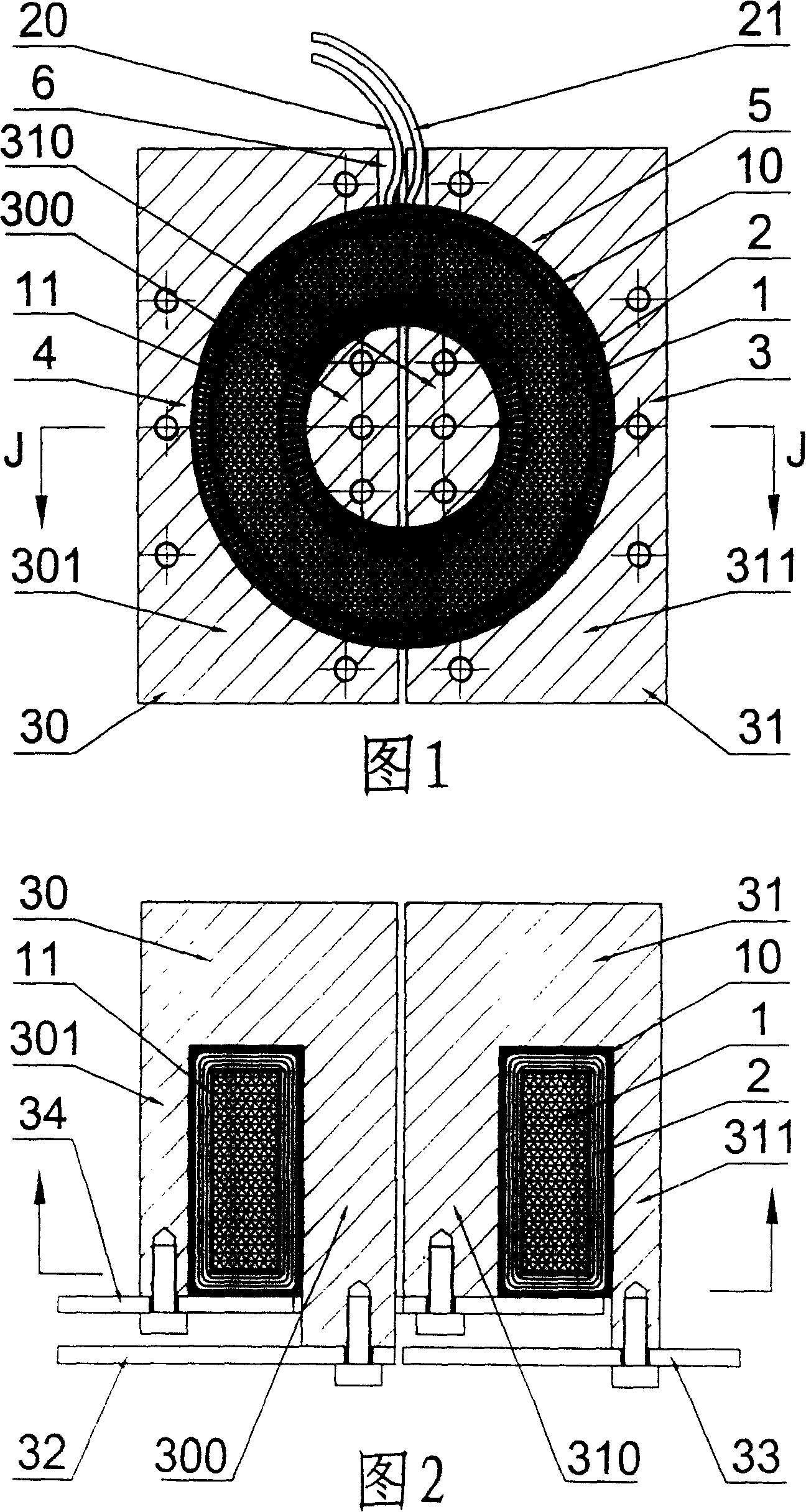
[0039] The left base body and the right base body are solid, and this kind of transformer adopts air-cooled cooling method.

Embodiment 2

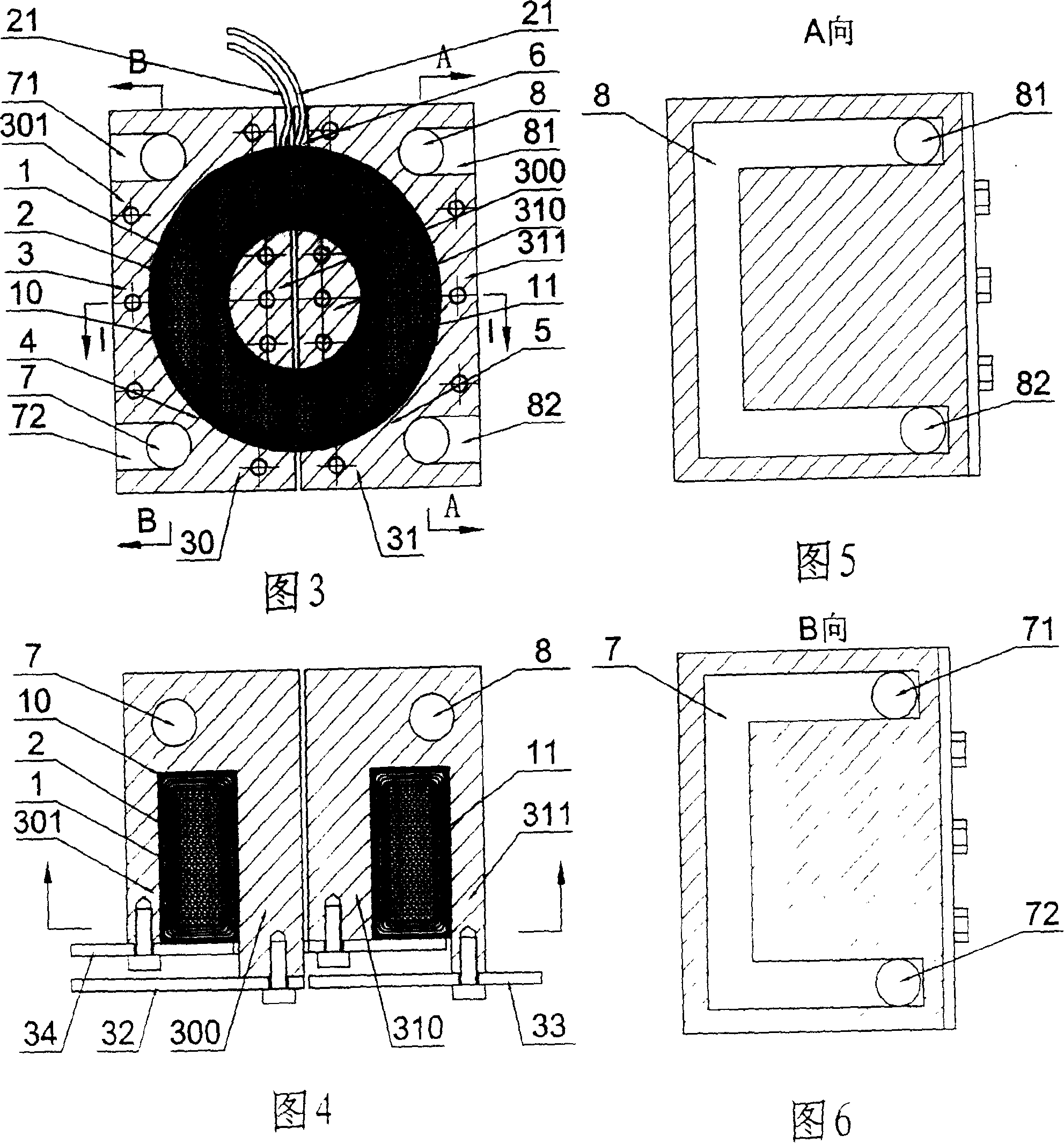
[0041] In the left base body 30, a left cooling chamber 7 is provided, and the left cooling chamber 7 is provided with an inlet 71 and an outlet 72 communicating with the outside; The inlet 81 and the outlet 82 communicated with the outside; the inlet is connected with the cooling device, the cooling material enters from the inlet, exchanges heat with the transformer, takes away a large amount of heat generated by the transformer, and then outputs it from the outlet, so that the transformer The temperature of the transformer is kept between 10°C and 20°C, so that the temperature rise of the transformer will not be too high; at the same time, it avoids the decrease of the load capacity, and even burns the transformer when the load is large or overloaded. Transformers of this structure can be cooled by fluid.

[0042] The working condition of the present invention is like this: connect the alternating voltage U at the primary side input terminal 1 , the alternating magnetic flu...


PUM


Abstract

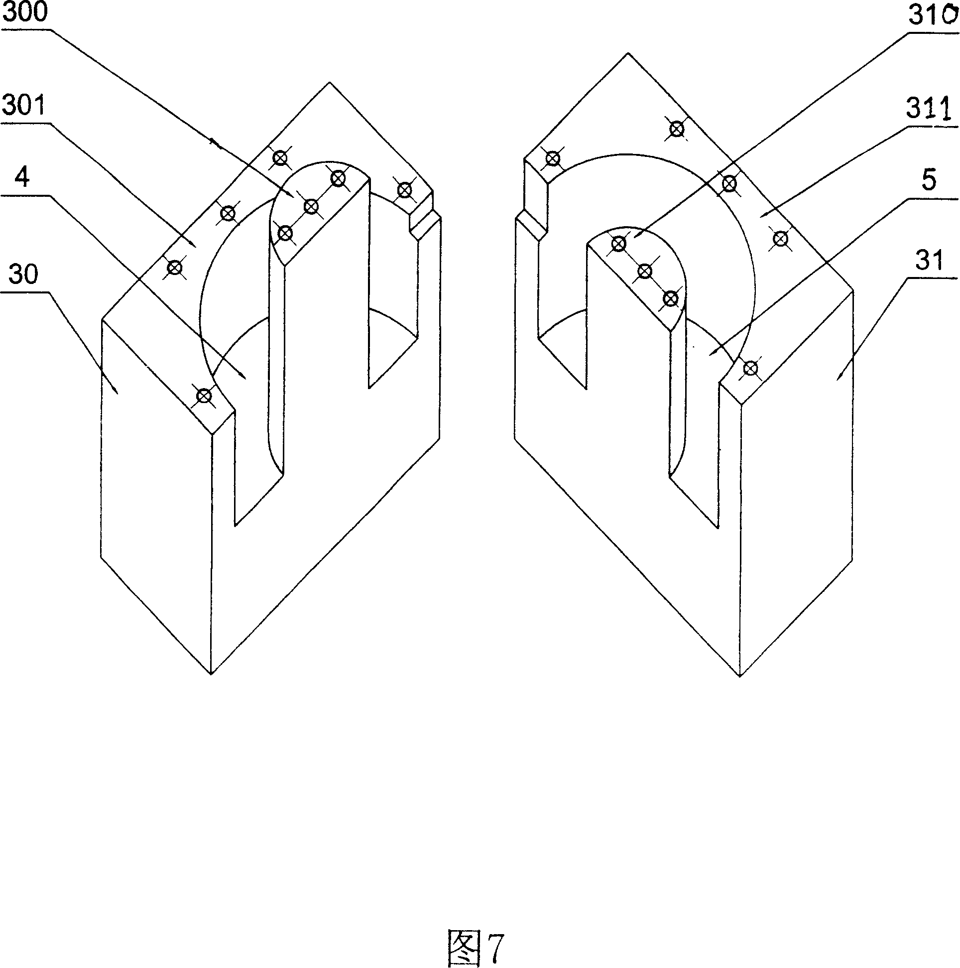
The invention discloses a new structure transformer, which belongs to the energy conversion installment. It completely avoids the welding, the big vice-side electric conduction area can realizes the output of the big electric current, the big cooling surface, the good radiation effect, the simple structure, the convenient service. The technical characteristic of the invention is that it includes the ferrite core, the primary side winding, vice-side, the vice-side is composed of left place body and the right place body, the left groove and the right groove separately opened on the left place body and the right place body, the left groove divides the left place body into the left stele and the left outside place body, the left stele and the left outside place body are connected in the base; the right groove divides the right place body into the right stele and the right outside place body, the right stele and the right outside place body are also connected in the base; the iron core placed in the groove, the primary side winding rolled around the iron core, the insulating layer has separately establishes between the primary side winding and the vice-side winding, between the primary side winding and the iron core.

Description

【Technical field】 [0001] The invention relates to a transformer. 【Background technique】 [0002] On March 4, 1998, the State Intellectual Property Office disclosed the "Transformer with Magnetic Material Protection Box Doubled as Low-Voltage Winding". The patent number is ZL96109545.8. The advantages of compactness and low loss. However, the processing of the above-mentioned patents must adopt welding technology, which requires high welding technology, and the insulation is difficult to handle, which increases the difficulty of manufacturing; while the secondary side adopts the shell type, the cross-sectional area is small, and it is not easy to realize the output of large current; This patent is not easy to achieve water cooling or air cooling. When the ambient temperature is high, the temperature of the transformer will rise and the load capacity will decrease. When the load is large or overloaded, the transformer will even be burned. [0003] These are undoubtedly heada...

Claims


Application Information

Patent Timeline
Patent Type & Authority Applications(China)
IPC IPC(8): H01F27/30H01F27/08
Inventor 卢桦岗田伍让
Owner 中山市华星电源科技有限公司
Learn More