RF identification system with restricted range

a technology of rf identification and restricted range, which is applied in the direction of burglar alarm mechanical actuation, using reradiation, instruments, etc., can solve the problems of inability of conventional rfid systems to direct information about a tag to the specific individual, etc., to reduce the communication range and minimize the possibility of responses

Inactive Publication Date: 2005-02-24
ROUND ROCK RES LLC
View PDF93 Cites 96 Cited by
  • Summary
  • Abstract
  • Description
  • Claims
  • Application Information

AI Technical Summary

Benefits of technology

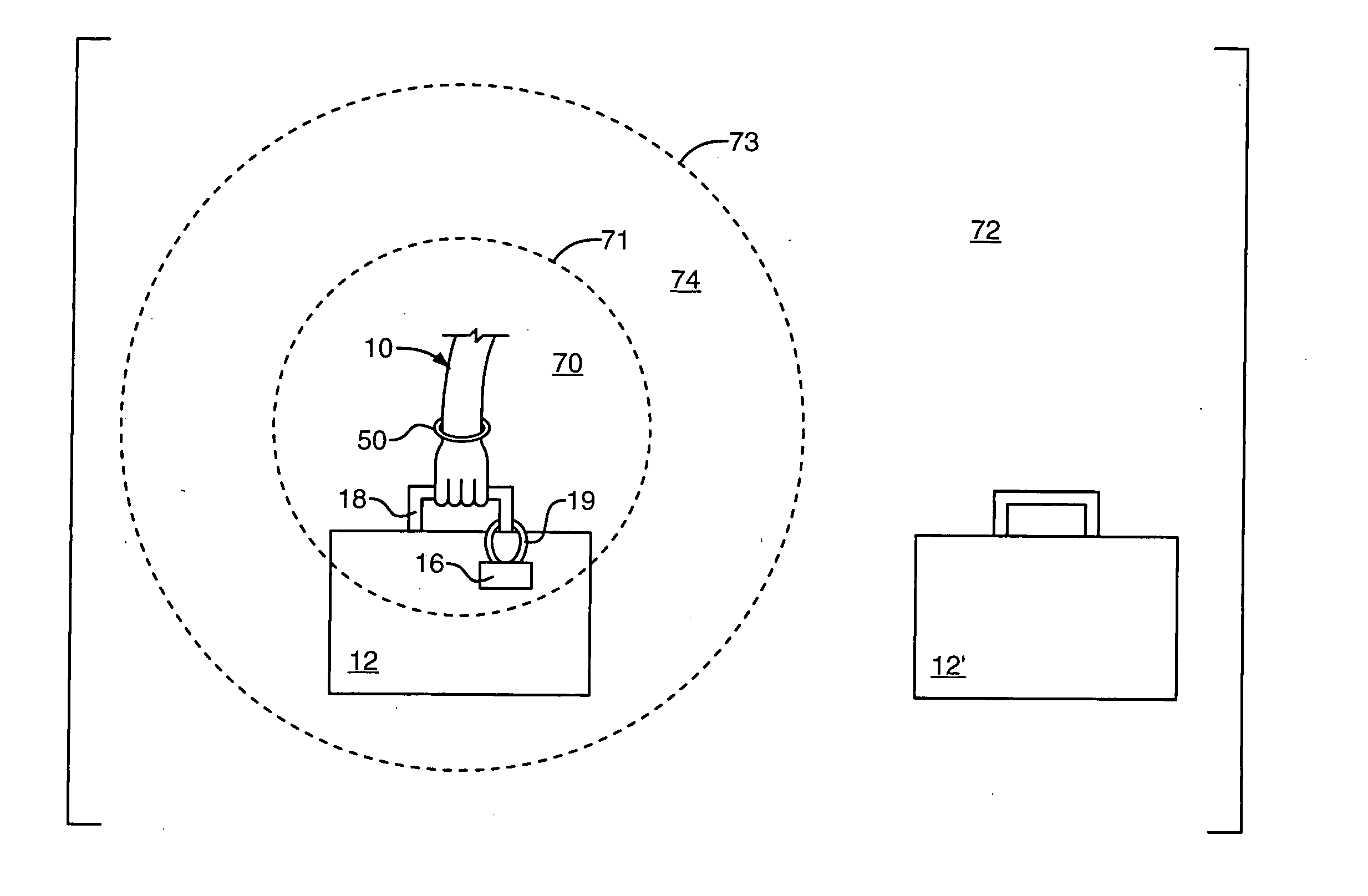
[0008] The interrogator transceiver can be mounted anywhere on the operator's person so as to leave both of the operator's hands free for handling the tagged objects. For example, the interrogator can be mounted on the person's belt. Furthermore, the interrogator can have an antenna mounted separately, preferably on the operator's wrist band or similarly near the person's hand, so that the operator can extend his hand toward a tagged object to bring the antenna within close communication range of the RFID tag on the object. This allows reducing the communication range so as to minimize the possibility of responses from RFID tags other than the one associated with the individual tagged object which the operator currently is hand

Problems solved by technology

Specifically, conventional RFID systems lack any means for discriminating in favor of an individual tagged object a human operator is working with at any given moment; instead, conventional RFID systems generally would confuse the operator by providing information regarding all the tagged objects in the vicinity.
Furthermore, if a number of personnel are working close to each other, conventional RFID systems cannot

Method used


Image

  • RF identification system with restricted range
  • RF identification system with restricted range
  • RF identification system with restricted range

Examples


Embodiment Construction

[0014] 1. Overview

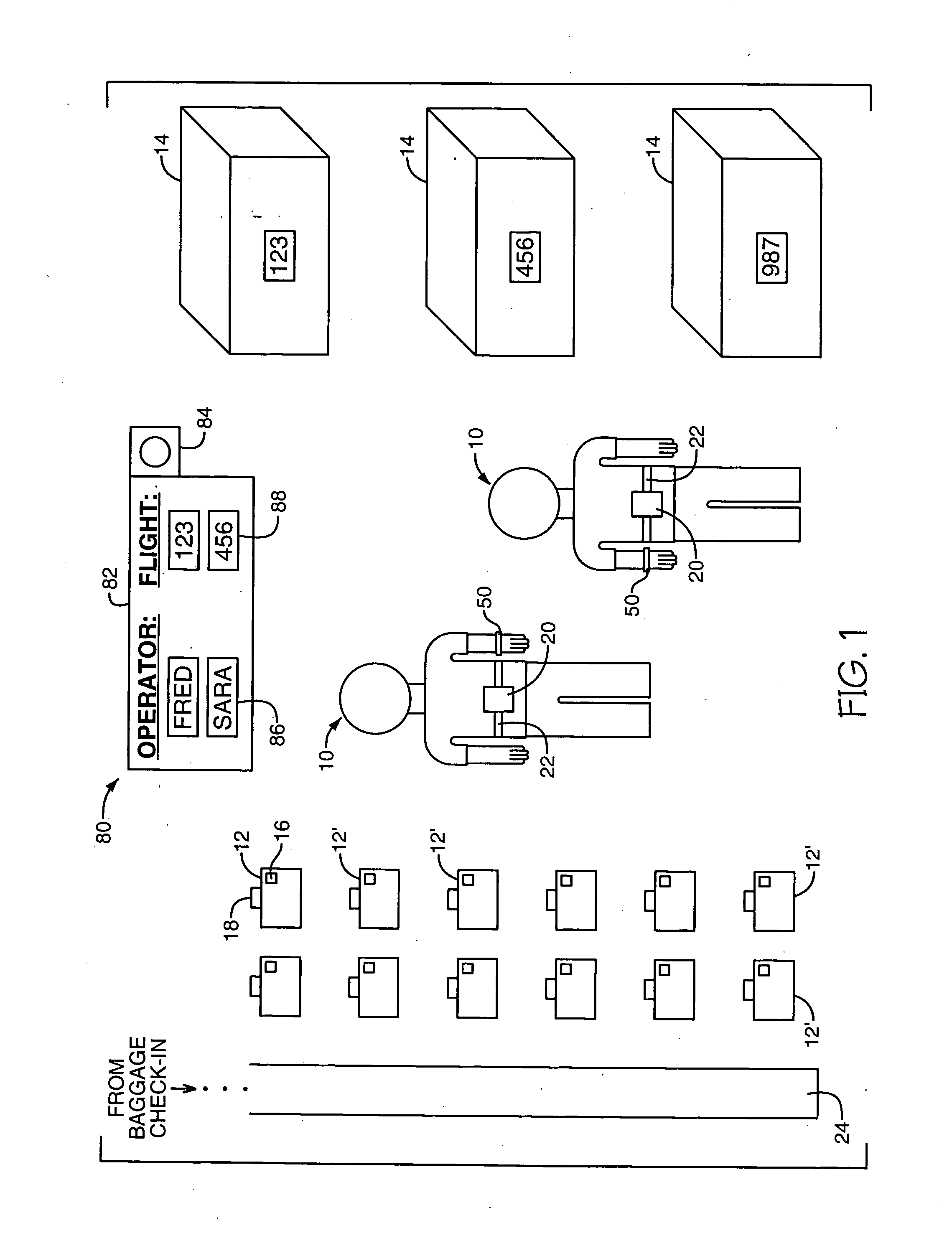
[0015] The invention will be described in the context of an exemplary implementation, depicted in FIG. 1, in which the human operators 10 are baggage handler personnel working in an airport baggage sorting facility, and the tagged objects 12 are airline baggage. However, the invention is equally applicable to any other objects to which RFID tags may be attached.

[0016] In the airport example, a number of baggage handler personnel 10, hereinafter called “operators”, are responsible for loading a large number of suitcases 12 and other baggage pieces into various freight containers 14, where each freight container has been designated to be loaded on a specific aircraft flight. An operator's job is to read the designated flight number and / or destination from a tag 16 attached to each suitcase and then to load the suitcase in the correct freight container.

[0017] Personnel at the airport passenger check-in counter attach an RFID tag 16 to each suitcase 12. Preferably, ...


PUM

PropertyMeasurementUnit
Poweraaaaaaaaaa
Sensitivityaaaaaaaaaa
Levelaaaaaaaaaa

Abstract

A method of adjusting the 2-way communication range of an RFID system to assist a human operator to individually handle and interrogate a plurality of tagged objects, such as suitcases, that each include an RFID tag transceiver. An RFID interrogator transceiver is mounted on the human operator. The 2-way communication range between the interrogator transceiver and the tag transceivers is adjusted to only slightly exceed the closest distance between the interrogator and the tag while the operator is handling the tagged object. Preferably, the 2-way communication range is short enough that other tagged objects will remain outside the communication range and will not respond to messages from the interrogator. Another aspect of the invention is a method of verifying whether an object to be transported has reached its intended destination. In this aspect, an interrogator transceiver at a first destination interrogates an RFID tag transceiver on the object, and in response the tag transmits its intended destination.

Description

FIELD OF THE INVENTION [0001] The invention relates generally to RF identification tags and interrogators, that is, to systems for identifying objects by communication between a radio frequency transceiver mounted on each object (RF identification “tag”) and a radio frequency transceiver “interrogator”. More specifically, the invention relates to such a system in which one or more human operators each has his own interrogator, and in which the 2-way communication range between each operator's interrogator transceiver and the tags is adjusted so as to prevent communications between the interrogator and more distant tags. BACKGROUND OF THE INVENTION [0002] Radio frequency identification (RFID) systems have been proposed for identifying tagged objects for such purposes as taking inventory or tracking movements of objects being transported. Examples are described in commonly assigned U.S. Pat. Nos. 5,300,875; 5,365,551; and 5,448,110. [0003] RFID systems generally employ a passive or ac...

Claims


Application Information

Patent Timeline
IPC IPC(8): B22D19/00B22F7/06G01S13/74G01S13/76G01S13/78G06K7/00G06K17/00G06K19/07G06K19/073G06K19/077G08B13/14H01H85/00H01H85/041H01H85/055H01H85/06H01Q1/22H01Q1/38H01Q9/28H04L29/12
CPCB07C7/005H04L61/6022B22F7/06G01S13/74G01S13/765G01S13/767G01S13/78G06K7/0008G06K7/10079G06K7/10217G06K7/10861G06K19/0723G06K19/073G06K19/07749G06K2017/0048G06Q10/08G06Q10/087G08B13/1427G08B13/149G08B21/0286H01Q1/22H01Q1/2225H01Q1/38H01Q9/28H01Q9/285H04L29/12254H04L29/12264H04L29/12292H04L29/12311H04L29/1232H04L29/12801H04L29/12839H04L61/2038H04L61/2046H04L61/2069H04L61/2084H04L61/2092H04L61/6004B22D19/00H04L61/5046H04L61/5069H04L61/5038H04L61/5092H04L61/5084H04L2101/604H04L2101/622
Inventor TUTTLE, JOHN R.
Owner ROUND ROCK RES LLC
Why Eureka
Try Eureka