Communication device
A communication device and signal technology, applied in circuit devices, electrical components, transmission systems, etc., can solve problems such as increased power consumption, difficulty in communication devices, and malfunctions
- Summary
- Abstract
- Description
- Claims
- Application Information
AI Technical Summary
Problems solved by technology
Method used
Image
Examples
Embodiment 1
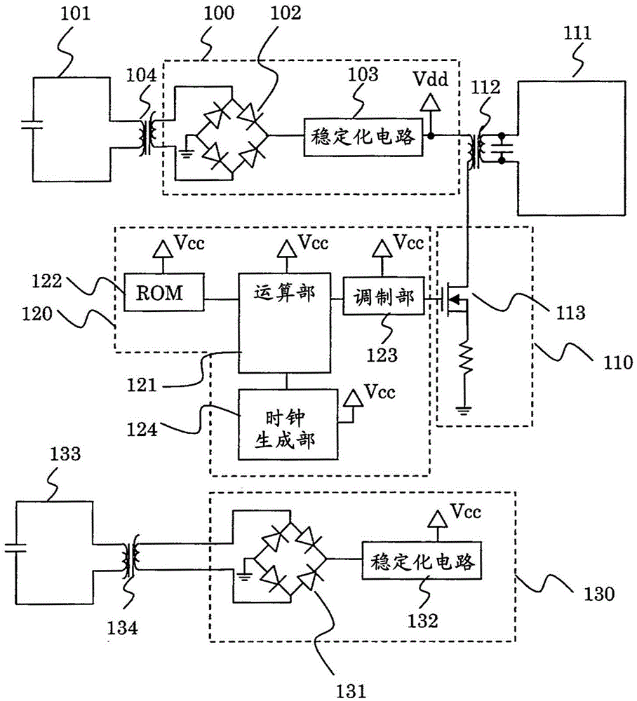
[0022] This example illustrates the following example, namely
[0023] A communication device that is powered by electric waves sent from the outside,
[0024] A plurality of radio wave systems are installed in the communication device, which supply electric power or signals obtained from the above-mentioned radio waves to the communication device,
[0025] The first radio wave system among the plurality of radio wave systems is connected so as to supply power to a circuit for driving a transmission element for transmitting a signal from the communication device,
[0026] Another radio wave system is connected to a signal generator for generating a signal transmitted by the communication device.
[0027] In addition, in this embodiment, an example of a communication device in which the impedance of the signal generation unit is set higher than the impedance of a circuit for driving the transmission element is also described.
[0028] An example of the communication device in...
Embodiment 2
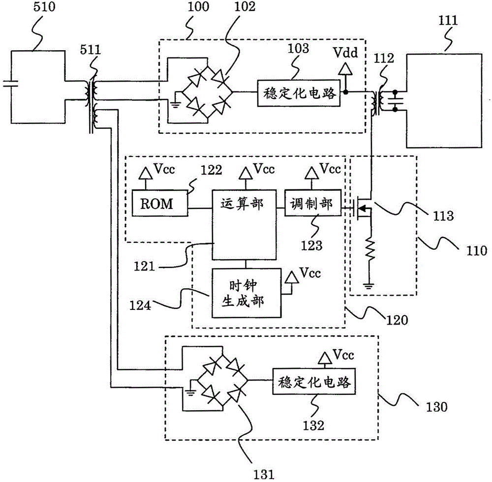
[0052] figure 2 It is an embodiment of the communication device, that is, a distribution transformer is connected to one radio wave receiving element that receives radio waves, and a plurality of radio wave systems are connected from the parts obtained by dividing into two or more by the distribution transformer.
[0053] Specifically, the second embodiment includes the rectification unit 100 , the rectification unit 130 , the signal wave transmission antenna 111 , the transmission antenna drive unit 110 , the signal generation unit 120 , and the conversion transformer 112 similarly to the first embodiment. In addition, a radio wave receiving antenna 510 and a distribution transformer 511 for distributing electric power received by the radio wave receiving antenna 510 are provided, and the electric power distributed by the distribution transformer 511 is input to the rectification unit 100 and the rectification unit 130 .
[0054] According to this embodiment, two rectified p...
Embodiment 3
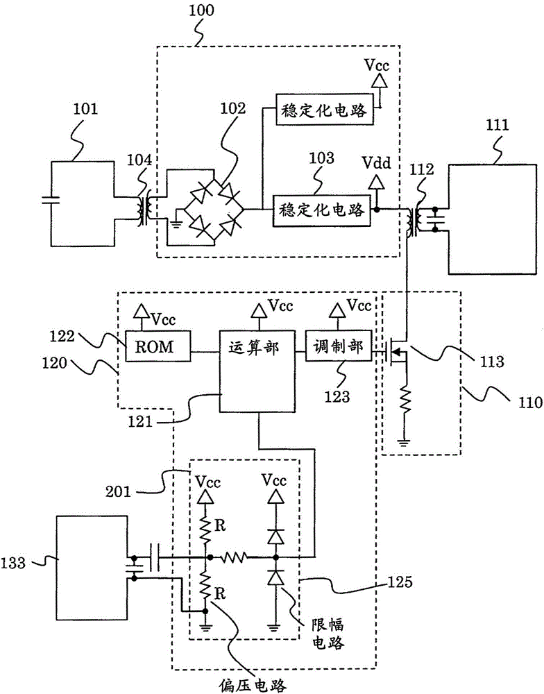
[0056] image 3 It is an embodiment of the communication device, that is, at least one of other radio wave systems is connected to the clock generating unit in the signal generating unit, and the clock obtained by regenerating the radio wave clock by the clock regeneration circuit is used as the clock of the communication device.
[0057] More specifically, Embodiment 3 includes the same as Embodiment 1: a first radio wave receiving antenna 101, a first rectifying unit 100, a signal wave transmitting antenna 111, a transmitting antenna driving unit 110, a signal generating unit 120, a conversion transformer 104, and a conversion transformer 104. The transformer 112 and the second radio wave receiving antenna 133 are connected to the clock regeneration circuit 201 . The clock regeneration circuit 201 regenerates the clock of the received radio wave, and inputs it to the calculation unit 121 . Calculation processing is performed by the clock input from the clock regeneration ci...
PUM
 Abstract
Description
Claims
Application Information
 - R&D
- Intellectual Property
- Life Sciences
- Materials
- Tech Scout
- Unparalleled Data Quality
- Higher Quality Content
- 60% Fewer Hallucinations
Browse by: Latest US Patents, China's latest patents, Technical Efficacy Thesaurus, Application Domain, Technology Topic, Popular Technical Reports.
© 2025 PatSnap. All rights reserved.Legal|Privacy policy|Modern Slavery Act Transparency Statement|Sitemap|About US| Contact US: help@patsnap.com


