L2 switch and control method therof

a control method and switch technology, applied in data switching networks, data switching details, multiplex communication, etc., can solve the problems of wasting trunk lines connected to the upper apparatuses of l2 switches, igmp snooping table overflow, and transferring multicast traffic to other users. to prevent attacks by a certain user

Inactive Publication Date: 2005-02-24
KDDI CORP
View PDF3 Cites 59 Cited by
  • Summary
  • Abstract
  • Description
  • Claims
  • Application Information

AI Technical Summary

Benefits of technology

[0024] According to the invention, it is possible to impartially assign multicast addresses to each user by limiting the number of data sources to be assigned to each output port of the switching engine. Furthermore, DoS attacks by a certain user can be prevented.

Problems solved by technology

In a conventional system to control multicast traffics only through updating of the IGMP snooping table, when several channel changes are carried out during a table-updating period, it causes the following problems.
Secondly, if a malicious user continuously transmits IGMP frame during an updating period of an IGMP snooping table, the IGMP snooping table overflows.
As a result, transferring of multicast traffics to the other users is jammed.
Thirdly, bandwidth of a trunk line connected to the upper apparatuses of the L2 switch are wasted because the multicast traffics of the addresses having stored due to the zapping are all transferred.
When a transfer request of the multicast traffics larger than the bandwidth of the trunk line, all the traffics connecting to any port are adversely affected due to the congestion of the trunk line.
Fourthly, under the circumstances, no new user can receive the multicast because it is unable to add a new entry to nor to update the IGMP snooping table.

Method used


Image

  • L2 switch and control method therof
  • L2 switch and control method therof
  • L2 switch and control method therof

Examples


Embodiment Construction

[0030] Explanatory embodiments of the invention are explained below in detail with reference to the drawings.

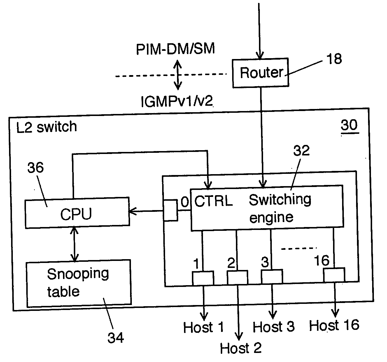
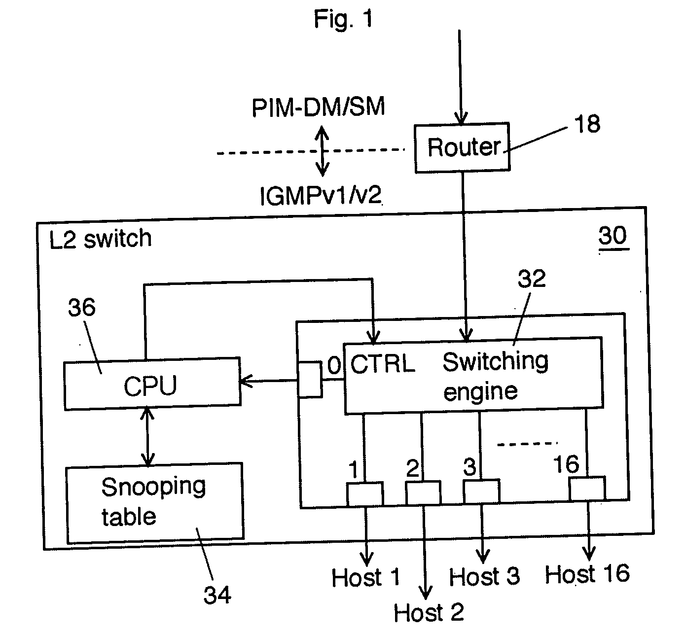
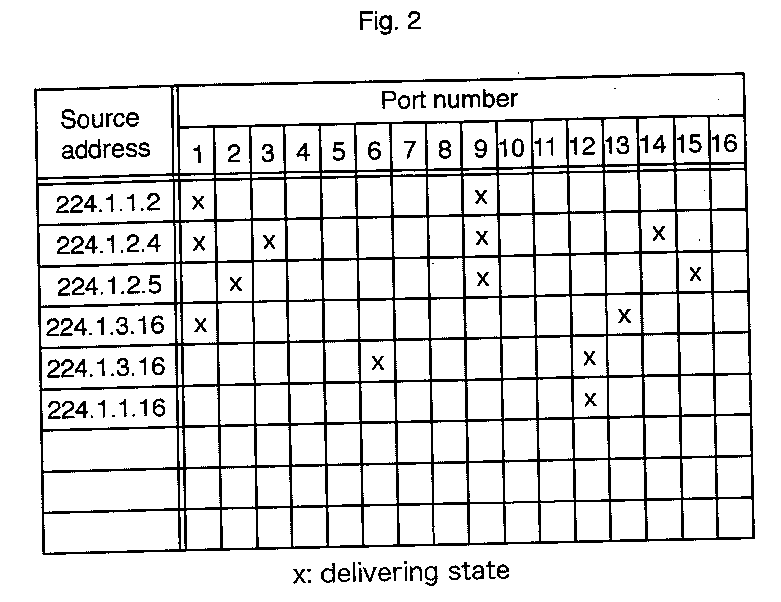
[0031]FIG. 1 shows a schematic block diagram of an L (layer) 2 switch according to an explanatory embodiment of the invention. FIG. 2 shows an example of an IGMP snooping transfer table used in the L2 switch shown in FIG. 1. An L2 switch 30 shown in FIG. 1 is disposed on the corresponding position where an L2 switch 20 shown in FIG. 3 is disposed.

[0032] The L2 switch 30 is composed of a switching engine 32 to actually deliver MAC frames between input ports and output ports, an IGMP snooping table 34, and a CPU (or switch controller) 36 to update the IGMP snooping table 34 and to control the switching engine 32 according to the contents of the IGMP snooping table 34.

[0033] The switching engine 32 snoops IGMPs communicated between a router 18 and user systems (host 1 to host 16) and informs it to the CPU 36 through a port 0. The CPU 36 updates the IGMP snooping table 34 acco...


PUM


Abstract

An L2 switch disposed between a multicast network and one or more user systems includes a switching engine having an input port to receive multicasted data from the multicast network and a plurality of output ports, the switching engine capable of delivering at least a part of the multicasted data from at least one of a plurality of data sources in the multicast network to one or more data-destination ports of the plurality of output ports; a transfer table to store corresponding relations between the at least one of the plurality of data sources and the one or more data-destination ports of the plurality of output ports; and a switching controller to update the transfer table according to a predetermined message that passes through the switching engine and to control the delivering of the multicasted data of the switching engine by referring to the transfer table. The switching controller limits a number of the plurality of data sources to be assigned to each output port of the switching engine within a predetermined number and refuses to update the transfer table for a delivery request that exceeds the predetermined number.

Description

CROSS REFERENCE TO RELATED APPLICATIONS [0001] This application claims priority to Japanese Patent Application No. 2003-294590, filed Aug. 18, 2003, the entire contents of which are incorporated herein by reference. FIELD OF THE INVENTION [0002] This invention relates to an L2 switch and a control method thereof. BACKGROUND OF THE INVENTION [0003] In a data network represented by IP network, multicast has been spotlighted as a service to take the place of broadcasting or similar services. Although there is a similar service called video on demand (VoD), multicast has a merit to consume fewer bandwidth compared to VoD. IP multicast using IGMP (Internet Group Management Protocol) is described in Japanese Laid-Open Patent application Nos. 2001-521716, 2000-125277, 2000-134208, 2002-44132, and 2002-64558. Japanese Laid-Open Patent application No. 2001-521716 corresponds to International publication No. WO98 / 48343 and Japanese Laid-Open Patent application No. 2000-125277 corresponds to U...

Claims


Application Information

Patent Timeline
Patent Type & Authority Applications(United States)
IPC IPC(8): H04L12/18H04L12/44H04L45/16H04L45/74H04L47/76
CPCH04L12/1886H04L49/351H04L49/201H04L45/16
Inventor TANAKA, KEIJIHASEGAWA, TERUYUKI
Owner KDDI CORP
Why Eureka
Try Eureka