Register for air conditioning

a register and air conditioner technology, applied in the field of registers, can solve the problems of poor appearance, low accuracy, dull appearance of the air conditioner register, etc., and achieve the effect of less likely to rattle and high accuracy

Active Publication Date: 2005-02-24
TOYODA GOSEI CO LTD
View PDF6 Cites 22 Cited by
  • Summary
  • Abstract
  • Description
  • Claims
  • Application Information

AI Technical Summary

Benefits of technology

[0009] The present invention has been developed and completed in view of such circumstances. It is therefore an object of the present invention to provide a register for air conditioning whose fin members are less likely to rattle and are controlled with high accuracy.

Problems solved by technology

Consequently, the conventional air-conditioning register 100 looks dull decoratively, and gives poor appearance.
Moreover, in the case of air-conditioning registers in which the lowest horizontal fin member is controlled by the sliding between the receiver and the recess groove alone, the receiver might not slide well in the recess groove because of the inaccurately molded component parts.

Method used


Image

  • Register for air conditioning
  • Register for air conditioning
  • Register for air conditioning

Examples


examples

[0032] Having generally described the present invention, a further understanding can be obtained by reference to the specific preferred embodiments which are provided herein for the purpose of illustration only and not intended to limit the scope of the appended claims. Hereinafter, the present invention will be described with reference to forms of embodying the present air-conditioning register applied to vehicles.

example no.1

Example No. 1

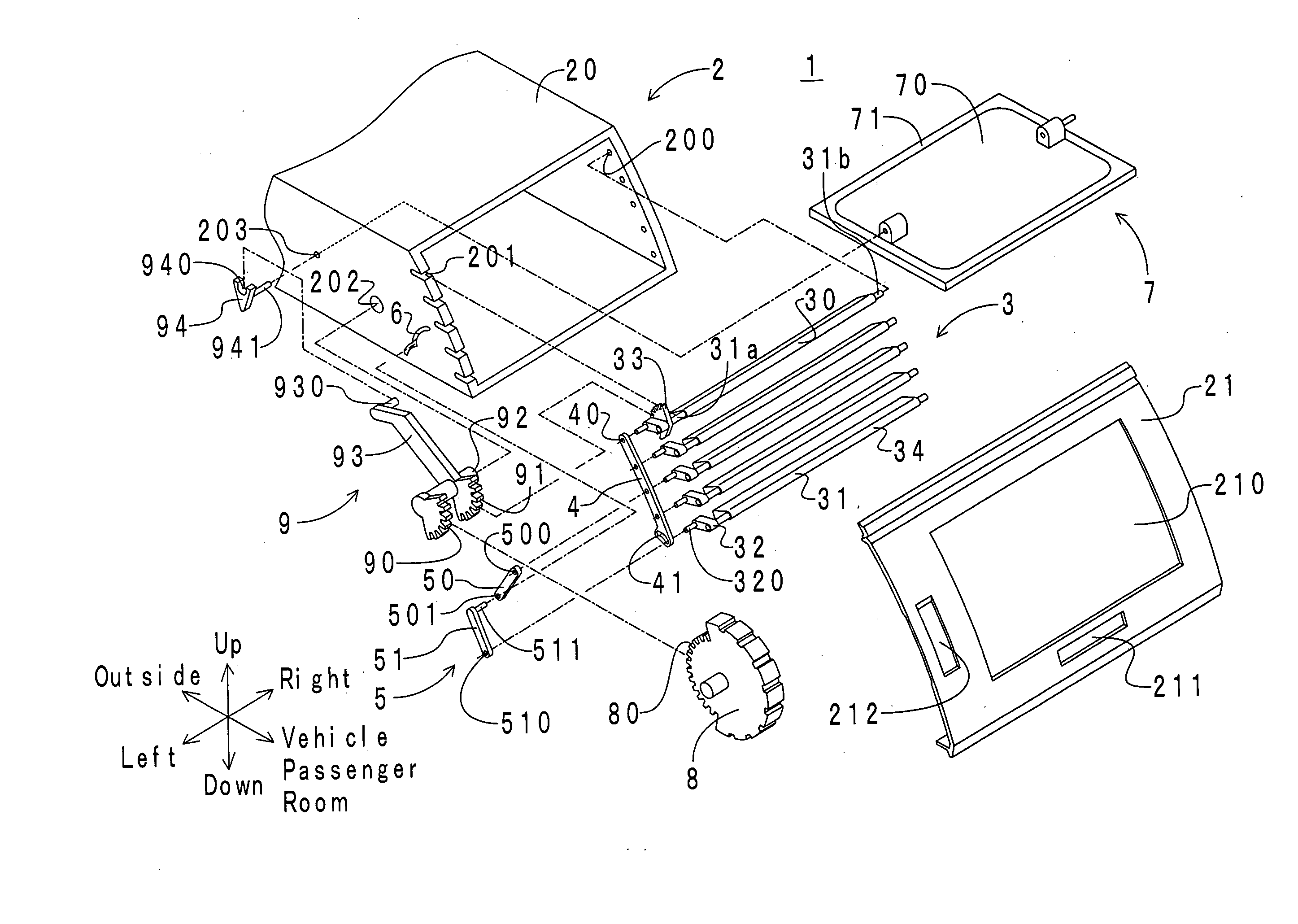
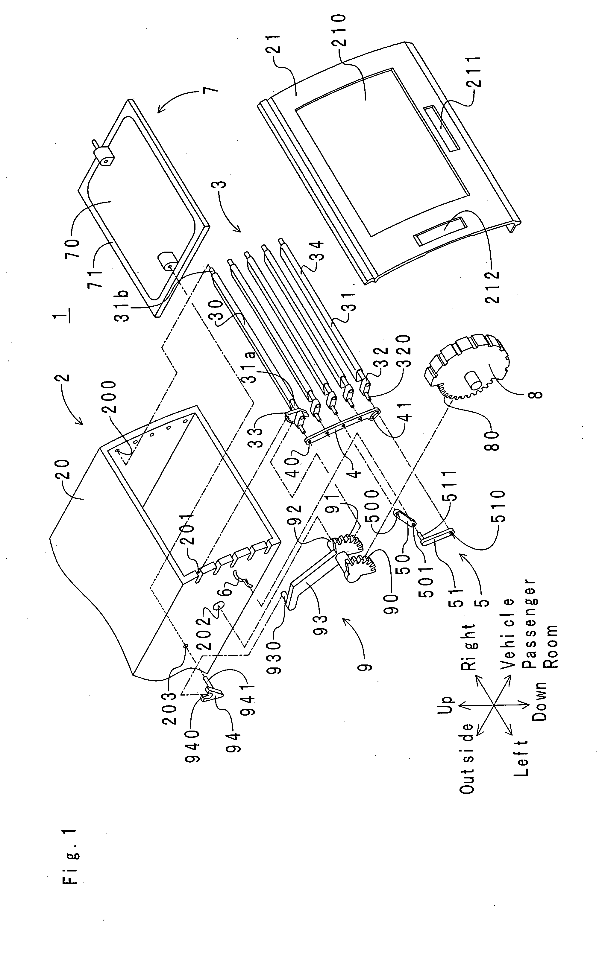
[0033] First, the arrangement of an air-conditioning.register according to Example No. 1 of the present invention will be hereinafter described in detail. FIG. 1 illustrates an exploded view of the air-conditioning register according to Example No. 1. As illustrated in the drawing, an air-conditioning register 1 comprises a retainer 2, a horizontal fin assembly 3, a connecting rod 4, a joint arm 5, a guide groove 6, a damper 7, a horizontal-fin operation dial 8, and a gear assembly 9. Note that the present fin assembly includes the horizontal fin assembly 3; the present first connector includes the connecting rod 4; the present second connector includes the joint arm 5; and the present guide includes the guide groove 6.

[0034] The retainer 2 comprises a retainer body 20, and a bezel 21. The retainer body 20 is made of resin, and is formed as a squared-cylinder shape. The retainer body 20 is connected with an air-conditioning duct (not shown) at the outer end with respec...

example no.2

Example No. 2

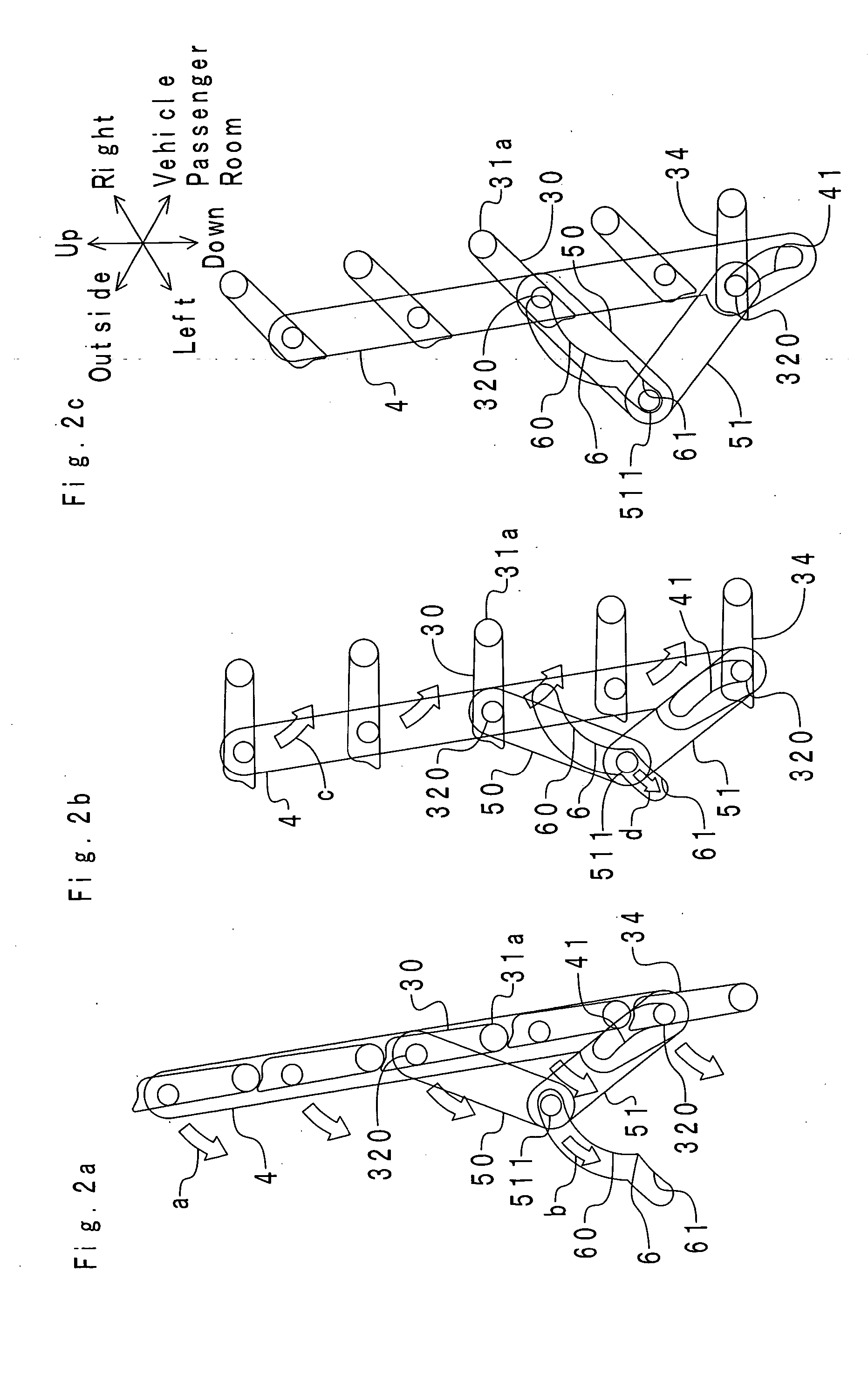
[0047] An air-conditioning register 1 according to Example No. 2 of the present invention differs from the air-conditioning register 1 according to Example No. 1 in that a swinging holder opening is disposed in the connecting rod instead of the swinging holder groove. Therefore, only the difference will be hereinafter described. FIGS. 3a, 3b and 3c illustrate a link mechanism for the air-conditioning register 1 according to Example No. 2. In FIGS. 3a, 3b and 3c, note that parts like those of FIGS. 2a, 2b and 2c are designated at the same reference numerals.

[0048] As illustrated in the drawing, a “C” -shaped swinging holder opening 42 is formed at the lower end of the connecting rod 4, instead of the swinging holder groove 41. When the swing angle of the dummy fin member 34 falls in a range of from the close position to the position for blowing the air-conditioning air substantially horizontally, the receiving shaft 320 of the dummy fin member 34 is held at a turnover p...


PUM


Abstract

An air-conditioning register includes a cylinder-shaped retainer having opposite inner surfaces, a fin assembly including a plurality of fin members disposed in the retainer, a first connector connecting the fin members, a second connector, and a guide guiding the second connector on a predetermined track. The fin members includes paired fin members disposed in proximity to the opposite inner surfaces of the retainer, at least one of the paired fin members swinging by a swing angle smaller than that of all of the other fin members, and functioning as a dummy fin member keeping a constant angle independently within a predetermined swing-angle range where all of the other fin members swing. The second connector connects the dummy fin member and all of the other fin members while absorbing a swing-angle difference between the dummy fin member and all of the other fin members.

Description

BACKGROUND OF THE INVENTION [0001] 1. Field of the Invention [0002] The present invention relates to a register for supplying air-conditioning air into vehicle passenger rooms, for example. [0003] 2. Description of the Related Art [0004]FIG. 6 illustrates a drawing of a link mechanism for a conventional register for air conditioning. The conventional air-conditioning register 100 comprises a retainer 101, a horizontal fin assembly 102, and a connecting rod 103. The retainer 101 comprises an outlet port 104 facing inwardly a vehicle passenger room. The horizontal fin assembly 102 comprises five horizontal fin members 102a. The horizontal fin members 102a comprise a swinging shaft 102b and a receiving shaft 102c. The receiving shafts 102c of the respective horizontal fin members 102 are connected with each other by the connecting rod 103. Hence, each of the horizontal fin members 102a swings about each of the swinging shafts 102b. [0005] In the conventional air-conditioning register 1...

Claims


Application Information

Patent Timeline
Patent Type & Authority Applications(United States)
IPC IPC(8): B60H1/34F24F13/15
CPCB60H1/3421B60H2001/3478B60H1/345
Inventor OKADA, MAKOTOOGURA, MITSUOASANO, KENJIKAKO, JUNICHIRO
Owner TOYODA GOSEI CO LTD
Why Eureka
Try Eureka