Furnace blower housing with integrally formed exhaust transition

a blower housing and exhaust transition technology, applied in the field of blower housings, can solve the problems of increasing and the labor to attach the transition piece to the blower assembly, so as to reduce the cost of the blower assembly and the associated, the effect of less labor intensive, and less expensiv

Inactive Publication Date: 2005-05-24
JAKEL MOTORS
View PDF20 Cites 17 Cited by
  • Summary
  • Abstract
  • Description
  • Claims
  • Application Information

AI Technical Summary

Benefits of technology

[0014]The two piece blower housing and exhaust transition of the present invention overcomes the disadvantages of the prior art. The invention provides for one of the exhaust transition sections to be part of the body. This piece is formed when the body is stamped and is formed of the same material as the body. Additionally, the second piece is also preferably formed of the same material as the body. Because the body is typically made of sheet metal, the first and second pieces of the exhaust transition are also made of sheet metal, which is significantly less expensive than the prior art transition pieces which are made of cast aluminum. The two pieces of the exhaust transition can be attached to one another by crimping one to the other. The crimping provides for a tight connection that will resist rattling better than the prior art use of sheet metal screws in attaching the transition piece to the body. Finally, the process of crimping is less labor intensive and further reduces the costs of manufacturing the housing over that of the prior art.

Problems solved by technology

Cast aluminum exhaust transition pieces are expensive to manufacture and increase the costs of the blower assembly and the associated furnace within which the blower assembly is utilized.
Because the exhaust transition piece is attached to the exhaust port for the blower housing by screws, the labor to attach the transition piece adds to the cost of the blower assembly.
Furthermore, because the exhaust transition piece is only secured to the blower housing by three or four screws, the connection often becomes loose over time and the exhaust transition piece may rattle or produce undesirable noise when the blower is being run.

Method used


Image

  • Furnace blower housing with integrally formed exhaust transition
  • Furnace blower housing with integrally formed exhaust transition
  • Furnace blower housing with integrally formed exhaust transition

Examples


Embodiment Construction

[0023]The use of the terms substantially and generally in the specification are meant to convey approximate shapes and orientations. The terms are not meant to limit the invention to precisely the shapes and orientations recited.

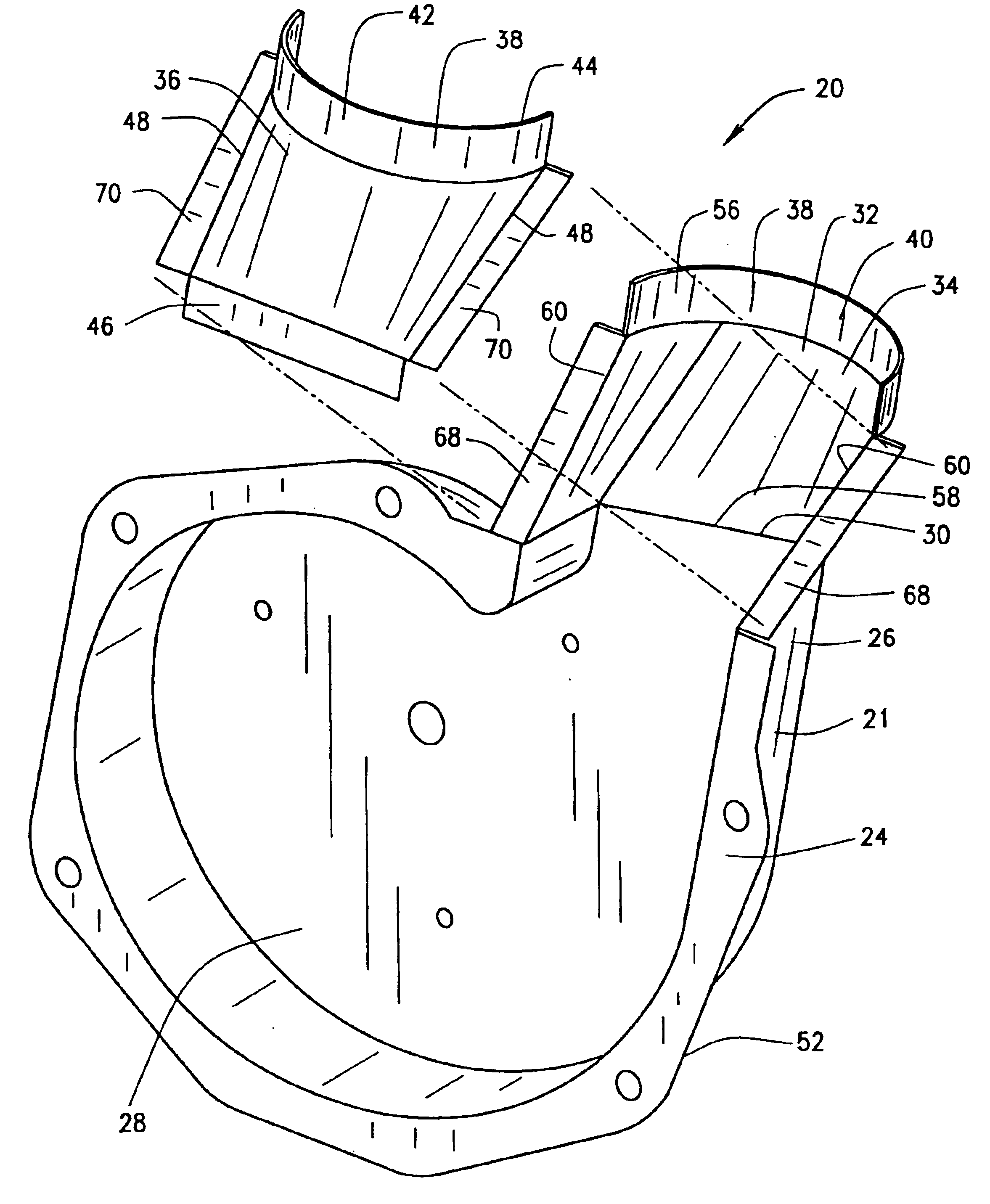
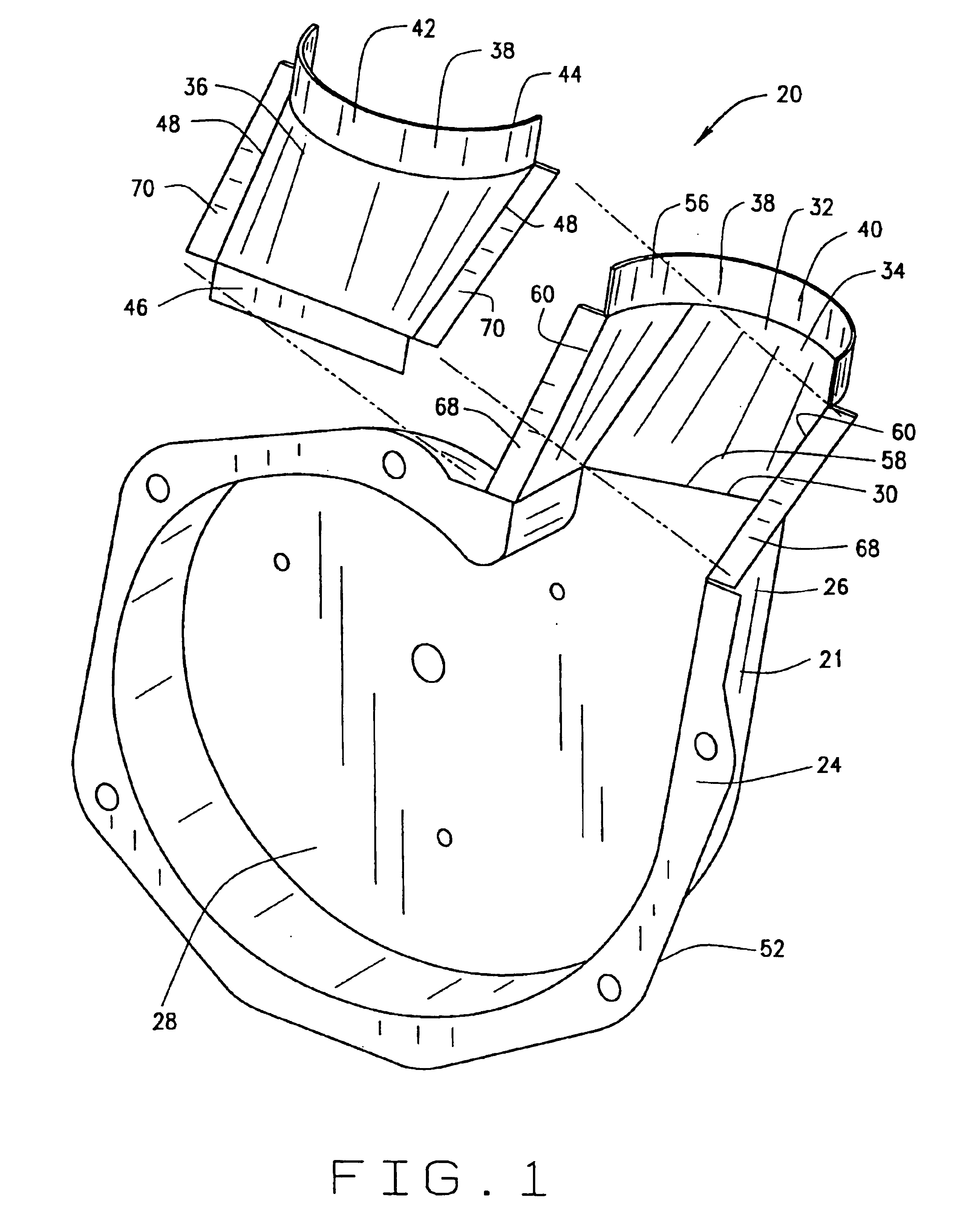
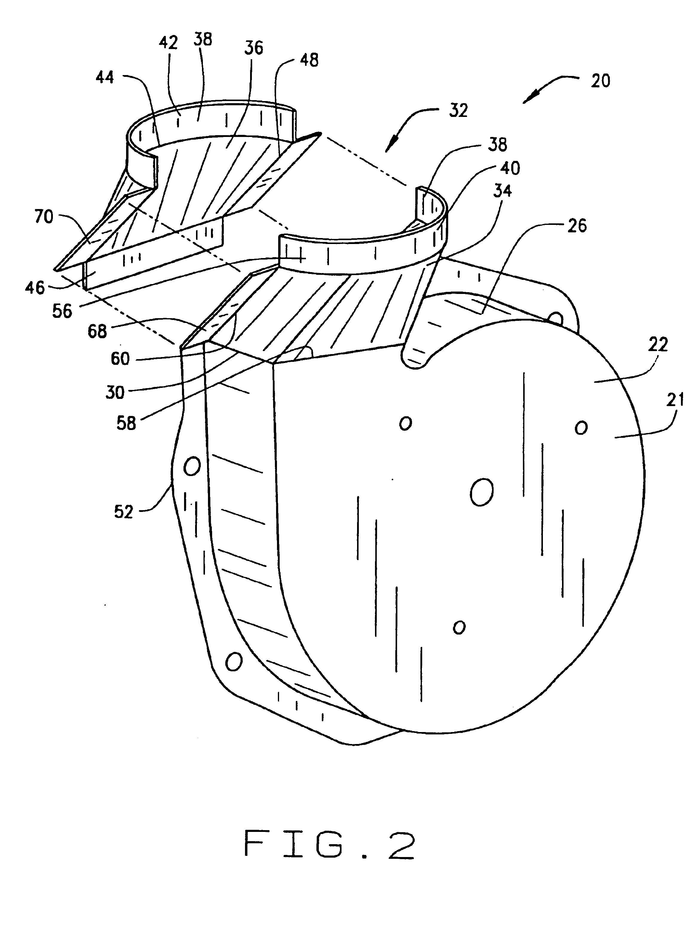
[0024]FIG. 1 shows the blower housing of the invention with the integrally formed portion of the exhaust transition generally indicated as 20. The housing 20 has a body 21 having a front wall 22 and a back wall or flange 24. A sidewall 26 extends between the front and back walls 22, 24. The sidewall 26 has a volute shape, which is typical of furnace blower housings and well known in the industry. The body 21 has a interior cavity 28 that is defined by the front and back walls 22, 24 and the sidewall 26. The cavity 28 is configured and adapted to house a fan (not shown) that rotates within the cavity 28 to generate a flow of air through the blower housing 20. The body 21 has a throat 30 that leads to an exhaust transition which is generally indicated as 32. T...


PUM


Abstract

A furnace blower housing has a two-piece exhaust transition, one piece of which is an integral extension of the blower housing, that transitions a rectangular cross section outlet of the blower housing to a circular cross section outlet of the exhaust transition that is adapted to be attached to a circular exhaust pipe.

Description

[0001]This patent application is a continuation of patent application Ser. No. 09 / 930,016 filed Aug. 15, 2001 now U.S. Pat. No. 6,595,146 which is a continuation of Ser. No. 09 / 651,645 filed Aug. 30, 2000 now U.S. Pat. No. 6,314,894.BACKGROUND OF THE INVENTION[0002](i) Field of the Invention[0003]The present invention relates in general to blower housings used in furnaces to remove the products of combustion and particularly to the exhaust transition of the blower housing. The blower housing includes an integrally formed portion of the exhaust transition and is of a two-piece construction.[0004](ii) Description of the Related Art[0005]Furnaces utilize a blower to induce a draft through the furnace to draw the heated air and the products of combustion through a heat exchanger and exhaust them through an exhaust pipe. The blower housings used in prior art furnaces are typically made of sheet metal and have an exhaust port that is rectangular. However, the exhaust pipe to which the blo...

Claims


Application Information

Patent Timeline
Patent Type & Authority Patents(United States)
IPC IPC(8): F01D25/24F01D25/26F04D29/44
CPCF01D25/24F04D29/441F01D25/265F05D2240/14
Inventor GATLEY, JR., WILLIAM STUART
Owner JAKEL MOTORS
Why Eureka
Try Eureka