Eureka AIR delivers breakthrough ideas for toughest innovation challenges, trusted by R&D personnel around the world.

Article Transport Apparatus and Article Transport Facility

a technology for transporting equipment and articles, applied in the direction of rollers, gearings, toothed gearings, etc., can solve the problems of poor transport efficiency, complex apparatus configuration in both structure and control, and the inability to receive the next product storage container, etc., to achieve simple apparatus configuration, good transport efficiency, and good durability

Active Publication Date: 2018-12-06
DAIFUKU CO LTD
View PDF8 Cites 4 Cited by
  • Summary
  • Abstract
  • Description
  • Claims
  • Application Information

AI Technical Summary

Benefits of technology

The technical effect of this patent is the creation of an article transport apparatus that has a simple structure and control, high transport efficiency, and good durability. The apparatus is designed to change the positions of supporting plates through the rotation of a supporting rotator, allowing for easy transport of articles. This design simplifies the apparatus and enables better control compared to other article transport apparatuses. The plurality of supporting plates are supported by a pair of supporting rotators that rotate around a single main shaft, reducing rippling and increasing durability. Overall, this patent proposes a new article transport apparatus with improved efficiency and durability.

Problems solved by technology

However, with the article transport apparatus disclosed in Patent Document 1, once the product storage container is raised using the raising / lowering mechanism, the next product storage container cannot be received until the raising / lowering mechanism is lowered again after picking is performed and the product storage container is carried out.
Therefore, there is a drawback in that transport efficiency is poor.
Moreover, while the raising / lowering mechanism is raised or lowered, the delivery portion (extractor assembly 32) of the article carry-out portion must be withdrawn from the picking position (pick area 23) in a timely manner so as not to interfere with the raising / lowering mechanism, and thus the apparatus configuration is complicated in terms of both structure and control.
Therefore, there is a drawback in that the supports are likely to rattle, and have poor durability.

Method used


Image

  • Article Transport Apparatus and Article Transport Facility
  • Article Transport Apparatus and Article Transport Facility
  • Article Transport Apparatus and Article Transport Facility

Examples


Embodiment Construction

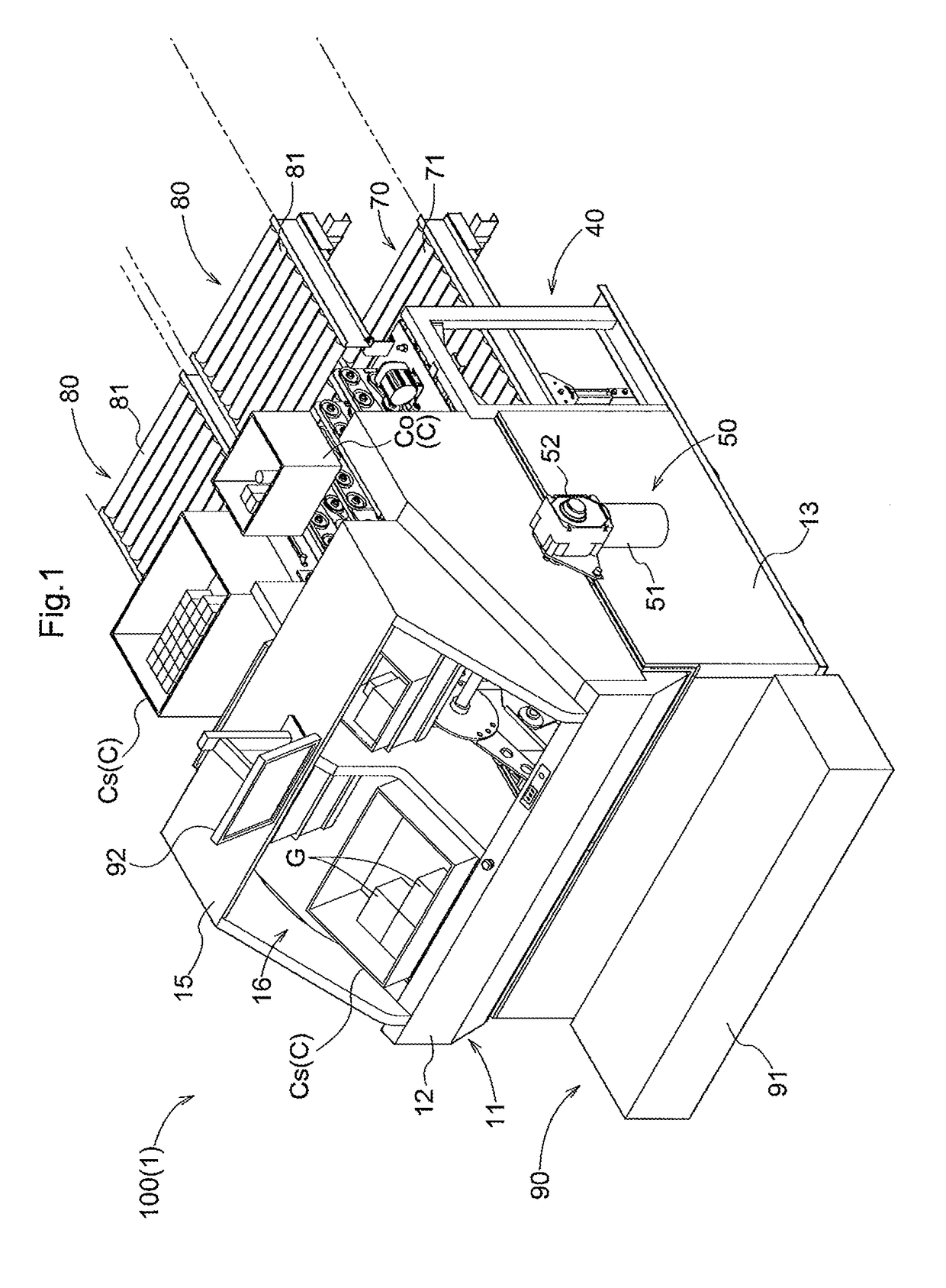
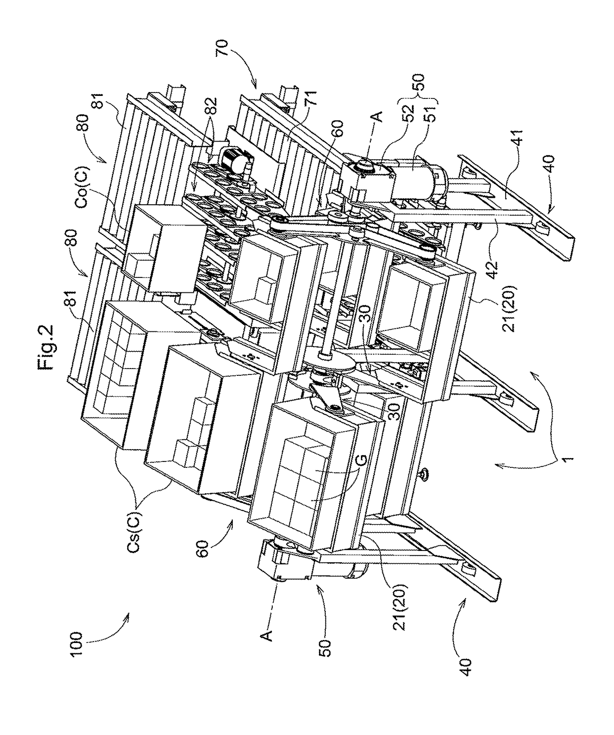
[0025]An embodiment of an article transport apparatus and an embodiment of an article transport facility will be described with reference to the drawings. These embodiments will be described using an article transport apparatus 1 incorporated in a picking facility and an article transport facility 100 as examples. The picking facility is used to collect, based on a picking order that specifies the type and the number of products G to be shipped, a specified number of a specific type of product G stored in a storage container C and taken out of an automatic warehouse in this state, and place the products G in a shipment container C. The article transport apparatus 1 and the article transport facility 100 are used to transport the containers C (i.e., empty containers or containers in which products G are stored, including storage containers Cs and shipment containers Co) as articles.

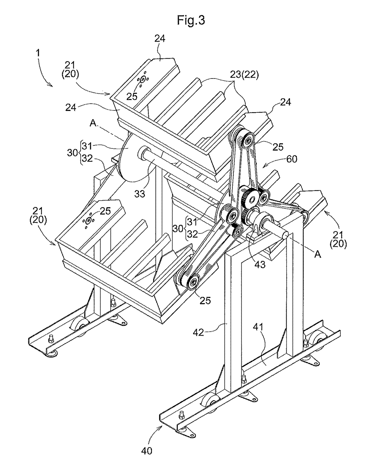
[0026]As shown in FIGS. 1 and 2, the article transport facility 100 includes two article transport appa...


PUM


Abstract

An article transport apparatus includes a plurality of supports, a supporting rotator that rotatably supports the supports at a plurality of positions, a driving portion for rotating the supporting rotator, an attitude maintenance mechanism for keeping the plurality of supports in a constant attitude irrespective of a phase of the supporting rotator, an article carry-in portion for carrying an article into the support located at a first position, and an article carry-out portion for carrying an article out of the support located at a second position.

Description

CROSS-REFERENCE TO RELATED APPLICATION[0001]This application claims priority to Japanese Patent Application No. 2017-106893 filed May 30, 2017, the disclosure of which is hereby incorporated in its entirety by reference.FIELD OF THE INVENTION[0002]The present invention relates to an article transport apparatus and an article transport facility.BACKGROUND[0003]Article transport apparatuses for transporting articles are used in picking stations in which articles are picked, for example. The specification of U.S. Pat. No. 8,713,899 (Patent Document 1) discloses an article transport apparatus (container-handling mechanism 22) for picking provided with a raising / lowering mechanism (elevator assembly 26). The article transport apparatus disclosed in Patent Document 1 is configured such that a product storage container (container T) supplied to a lower portion of the apparatus is raised to an upper portion of the apparatus using the raising / lowering mechanism, required products are picked ...

Claims


Application Information

Patent Timeline
Patent Type & Authority Applications(United States)
IPC IPC(8): B65G29/02B65G47/57B65G17/12B65G23/08F16H7/20
CPCB65G29/02B65G47/57B65G17/123B65G23/08F16H7/20B65G23/44F16H2007/0865B65G13/06B65G47/24B65G2201/0235F16H1/06F16H7/00B65G2201/02
Inventor HATANAKA, HIDEYASU
Owner DAIFUKU CO LTD
Why Eureka
Eureka Blog
Learn More