Cordless stethoscope for hazardous material environments

a stethoscope and hazardous material technology, applied in the field of stethoscopes, can solve the problems of not providing a stethoscope device compatible with hazardous material environments, putting medical personnel at risk, and destroying the purpose of wearing a sui

Inactive Publication Date: 2005-02-24
SAUERLAND KEITH A
View PDF9 Cites 14 Cited by
  • Summary
  • Abstract
  • Description
  • Claims
  • Application Information

AI Technical Summary

Benefits of technology

[0016] The sound sensing device comprises a fluid tight housing, a power source, a stethoscope head, a momentary activation switch, a microphone, a microphone activation switch and a transmitter. The sound sensing device is designed to be completely fluid tight so that the device may be decontaminated after use in a hazardous material environment without damaging the inner components of the device. The overall size and shape of the housing allows a user wearing gloves to compensate for the loss of fine motor skills.

Problems solved by technology

Breaking the protective barrier of the HAZMAT suit defeats the purpose of wearing the suit and places medical personnel at risk.
There are devices in the prior art that convey auscultatory information gathered by a stethoscope head in ways other than a standard stethoscope, but it has come to my attention that the prior art does not provide a stethoscope device compatible with hazardous material environments.
However, this device does not address important concerns that are particular to hazardous material environments such as providing a device that is water tight so that it may be easily decontaminated after use in a hazardous material environment or providing a stethoscope head that is easily used while wearing gloves commonly employed by HAZMAT suits.
However, this system does not provide a self contained and portable stethoscope device that can be used without other support structures in place and does not address the previously mentioned shortcomings that are particular in a hazardous material environment.

Method used


Image

  • Cordless stethoscope for hazardous material environments
  • Cordless stethoscope for hazardous material environments
  • Cordless stethoscope for hazardous material environments

Examples


Embodiment Construction

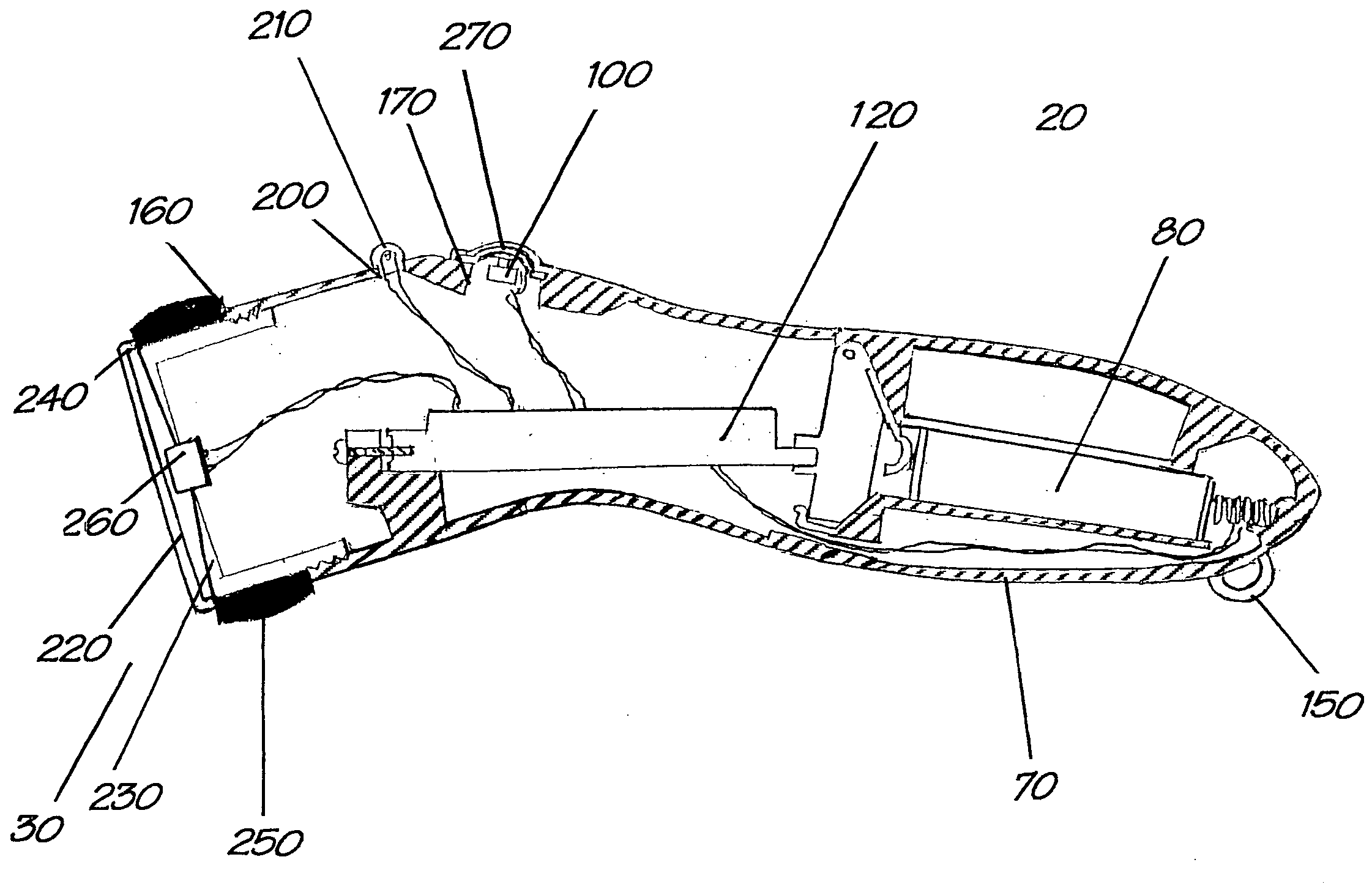
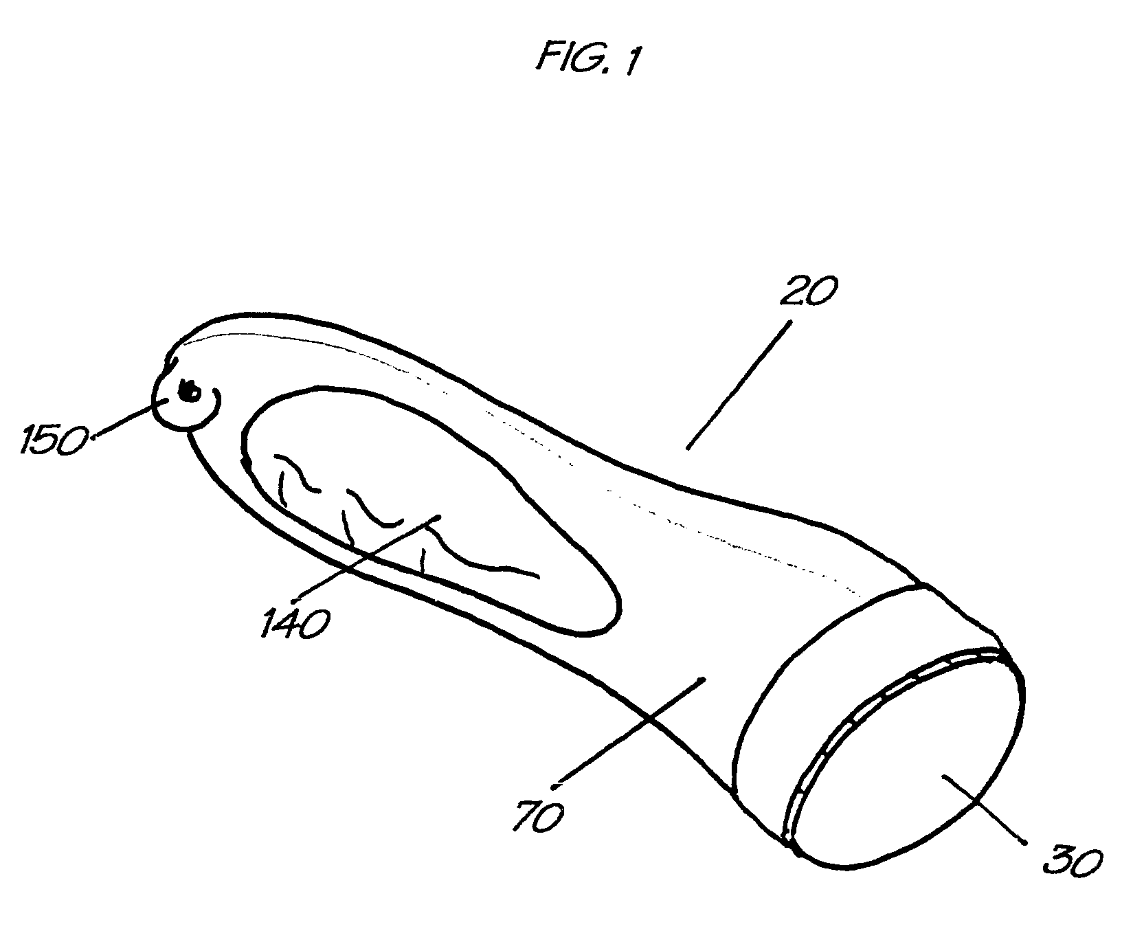
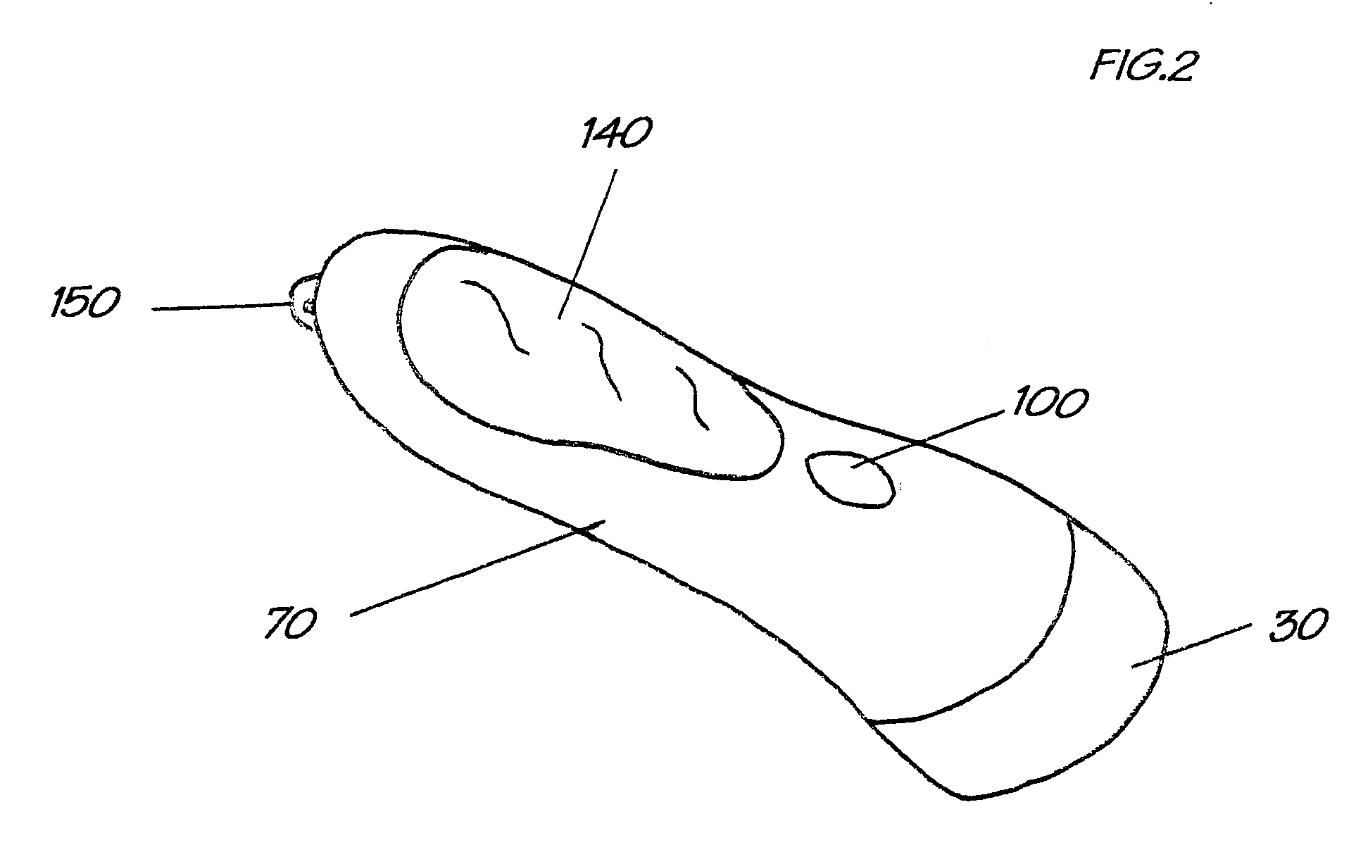
[0027] Turning now to the drawing figures, FIG. 8 shows the cordless stethoscope for use in hazardous material environments 10. The cordless stethoscope 10 generally comprises a sound sensing device 20 shown in FIGS. 1-4 having a stethoscope head 30 and a microphone 40 for sensing and transmitting sounds from a patient, a receiver 50 for receiving the transmissions, and earpieces 60 for converting the received transmissions into audible sound for the person using the cordless stethoscope 10.

[0028] The sound sensing device 20 shown in FIGS. 1-4 generally comprises a fluid tight housing 70, a power source 80, a stethoscope head 30, a momentary activation switch 100, a microphone 40, a microphone activation switch 110 and a transmitter 120. The sound sensing device 20 is designed to be completely fluid tight so that the device 20 may be decontaminated after use in a hazardous material environment without damaging the inner components of the device 20.

[0029] Heavy gloves are a necessa...


PUM


Abstract

A cordless stethoscope for use in hazardous material environments comprising a fluid tight hand held sound sensing device having a stethoscope head for sensing auscultatory sounds, a transmitter for transmitting sounds sensed by the device, a receiver for receiving transmissions from the transmitter and an ear piece for converting the received transmissions into audible sound. The housing is sized and shaped for being grasped by a gloved hand and is fluid tight for decontamination purposes. The sound sensing device may further comprise a microphone for sensing otherwise inaudible voice communications from a patient. The transmitter and receiver preferably uses magnetic induction transmissions to transmit sounds through barriers such as hazardous material suits that may be worn by clinicians during treatment of patients in possible hazardous material situations.

Description

BACKGROUND OF THE INVENTION [0001] 1. Field of the Invention [0002] The claimed invention generally relates to stethoscopes. More specifically, the claimed invention relates to cordless or wireless stethoscopes. [0003] 2. Description of the Prior Art [0004] The threat of rapidly spreading infectious diseases to many different places around the world with little or no notice has significantly increased as international air travel has become commonplace. This threat coupled with increased concerns about possible biological and chemical attacks have resulted in a general increase in the awareness and preparedness of medical personnel to combat these types of threats. Doctors, nurses and emergency medical technicians typically use hazardous material protection suits, commonly known as HAZMAT suits, to protect themselves against these threats. HAZMAT suits completely isolate the healthcare workers from the surrounding environment forming a protective barrier against biological and chemic...

Claims


Application Information

Patent Timeline
Patent Type & Authority Applications(United States)
IPC IPC(8): A61B5/00A61B7/04
CPCA61B5/0002A61B2560/0219A61B7/04
Inventor SAUERLAND, KEITH A.
Owner SAUERLAND KEITH A
Why Eureka
Try Eureka