Combustion liner cap assembly for combustion dynamics reduction

a technology of combustion dynamics and combustion liner, which is applied in the direction of machines/engines, mechanical equipment, lighting and heating apparatus, etc., can solve the problems of increasing repair costs, preventing the operation of combustion systems at the optimum (lowest) emissions level, and forced outage of gas turbines, so as to achieve the effect of reducing combustion dynamics

Active Publication Date: 2005-03-03
GENERAL ELECTRIC CO
View PDF9 Cites 17 Cited by
  • Summary
  • Abstract
  • Description
  • Claims
  • Application Information

AI Technical Summary

Benefits of technology

[0008] In another exemplary embodiment of the invention, a method of decreasing combustion dynamics in a gas turbine includes the steps of providing the combustion liner cap assembly, and forming a second set of circumferentially spaced cooling holes through the cylindrical outer sleeve, wherein the second set of cooling holes is axially spaced from the first set of cooling holes.

Problems solved by technology

High combustion dynamics in a gas turbine combustor can cause disadvantages such as preventing operation of the combustion system at optimum (lowest) emissions levels.
High dynamics can also damage hardware to a point that could result in a forced outage of the gas turbine.
Hardware damage that does occur but does not cause a forced outage increases repair costs.
Limitations do exist, however, as it is not only combustion dynamics that must be considered when tuning fuel splits or adjusting control settings.
Also costly and time-consuming, this option has the disadvantage of having only a certain range of application based on the design pressure ratio range of the nozzle.
The design space is typically a last resort in dynamics mitigation at this stage due to the high cost normally associated with the development of a new piece of hardware.

Method used


Image

  • Combustion liner cap assembly for combustion dynamics reduction
  • Combustion liner cap assembly for combustion dynamics reduction
  • Combustion liner cap assembly for combustion dynamics reduction

Examples


Embodiment Construction

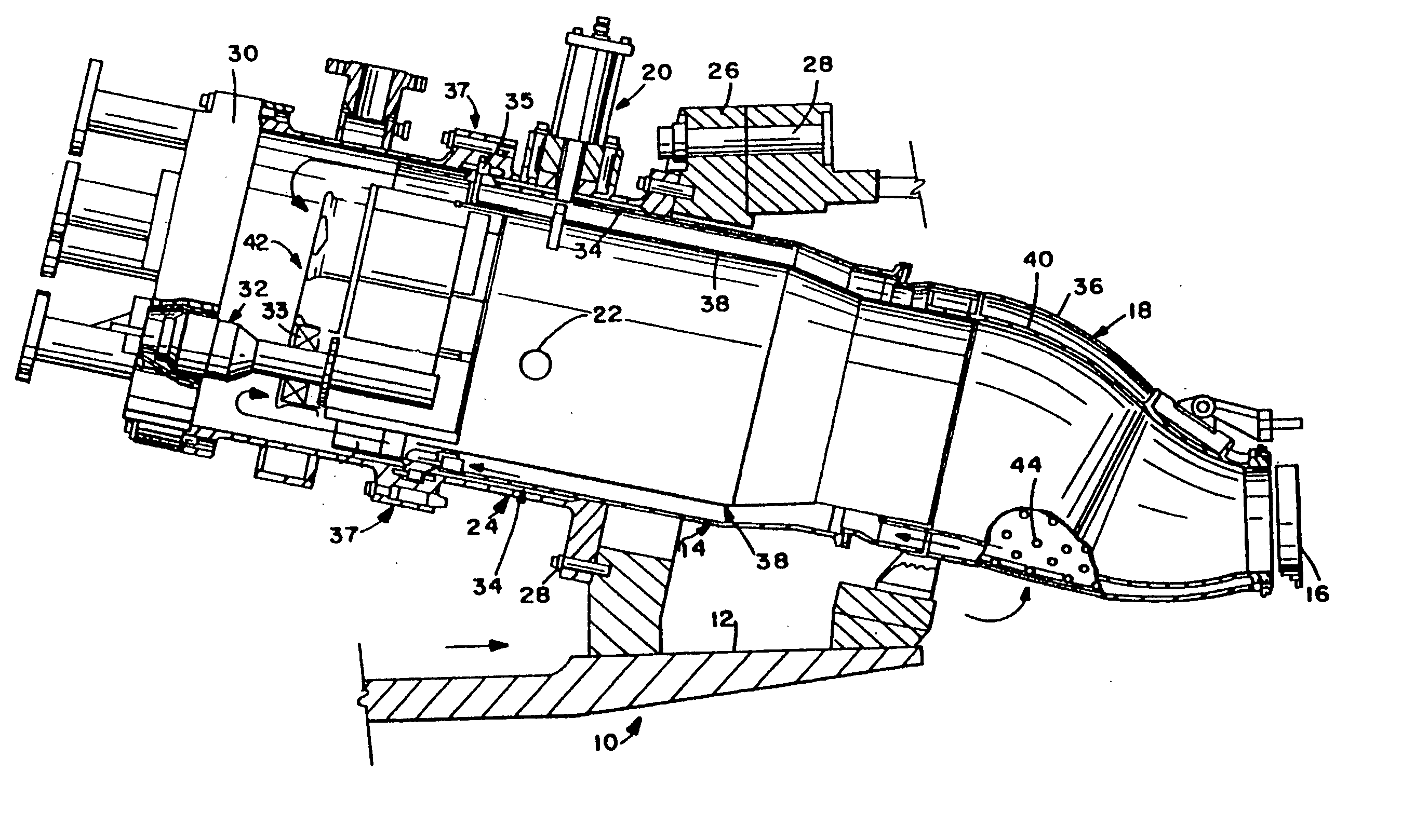
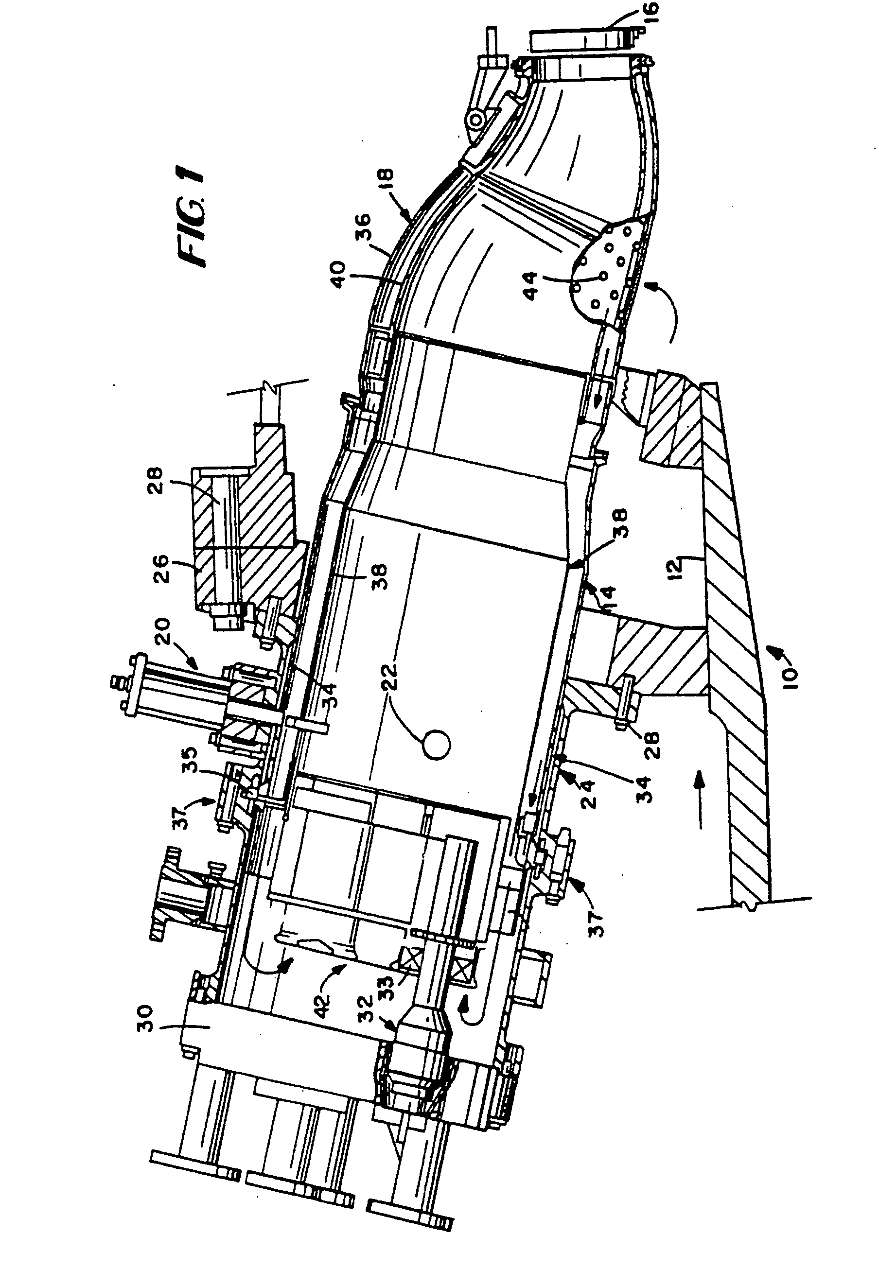
[0013] With reference to FIG. 1, the gas turbine 10 includes a compressor 12 (partially shown), a plurality of combustors 14 (one shown), and a turbine represented here by a single blade 16. Although not specifically shown, the turbine is drivingly connected to the compressor 12 along a common axis. The compressor 12 pressurizes inlet air which is then reverse flowed to the combustor 14 where it is used to cool the combustor and to provide air to the combustion process.

[0014] As noted above, the gas turbine includes a plurality of combustors 14 located about the periphery of the gas turbine. A double-walled transition duct 18 connects the outlet end of each combustor with the inlet end of the turbine to deliver the hot products of combustion to the turbine.

[0015] Ignition is achieved in the various combustors 14 by means of spark plug 20 in conjunction with cross fire tubes 22 (one shown) in the usual manner.

[0016] Each combustor 14 includes a substantially cylindrical combustion...


PUM

PropertyMeasurementUnit
diameteraaaaaaaaaa
combustion dynamicsaaaaaaaaaa
heat rateaaaaaaaaaa

Abstract

A combustion liner cap assembly includes a cylindrical outer sleeve supporting internal structure therein and a plurality of fuel nozzle openings formed through the internal structure. A first set of circumferentially spaced cooling holes is formed through the cylindrical outer sleeve, and a second set of circumferentially spaced cooling holes is formed through the cylindrical outer sleeve. The second set of cooling holes is axially spaced from the first set of cooling holes. The resulting construction serves to decrease combustion dynamics in a simplified manner that is retrofittable to current designs and reversible without impacting the original configuration. The reduction in combustion dynamics improves hardware life, which leads to reduced repair and replacement costs.

Description

BACKGROUND OF THE INVENTION [0001] The invention relates to gas and liquid fueled turbines and, more particularly, to combustors and a combustion liner cap assembly in industrial gas turbines used in power generation plants. [0002] A combustor typically includes a generally cylindrical casing having a longitudinal axis, the combustor casing having fore and aft sections secured to each other, and the combustion casing as a whole secured to the turbine casing. Each combustor also includes an internal flow sleeve and a combustion liner substantially concentrically arranged within the flow sleeve. Both the flow sleeve and combustion liner extend between a double walled transition duct at their forward or downstream ends with a sleeve cap assembly (located within a rearward or upstream portion of the combustor) at their rearward ends. The flow sleeve is attached directly to the combustor casing, while the liner receives the liner cap assembly which, in turn, is fixed to the combustor cas...

Claims


Application Information

Patent Timeline
Patent Type & Authority Applications(United States)
IPC IPC(8): F23M20/00F23R3/14F23R3/28F23R3/60
CPCF23R3/283F23R3/286F23M20/005F23R2900/00014Y10T29/49348F23R3/60
Inventor CRAWLEY, BRADLEY DONALDFOSSUM, JAMES
Owner GENERAL ELECTRIC CO
Why Eureka
Try Eureka