Electric tool

Inactive Publication Date: 2005-03-03
MATSUSHITA ELECTRIC WORKS LTD
View PDF5 Cites 29 Cited by
  • Summary
  • Abstract
  • Description
  • Claims
  • Application Information

AI Technical Summary

Benefits of technology

[0006] Therefore, a concern of the present invention is to provide an elect

Problems solved by technology

Consequently, it will lead to a considerable decrease in working efficienc

Method used


Image

  • Electric tool
  • Electric tool
  • Electric tool

Examples


Embodiment Construction

[0033] Electric tools according to preferred embodiments of the present invention are explained in detail referring to the attached figures.

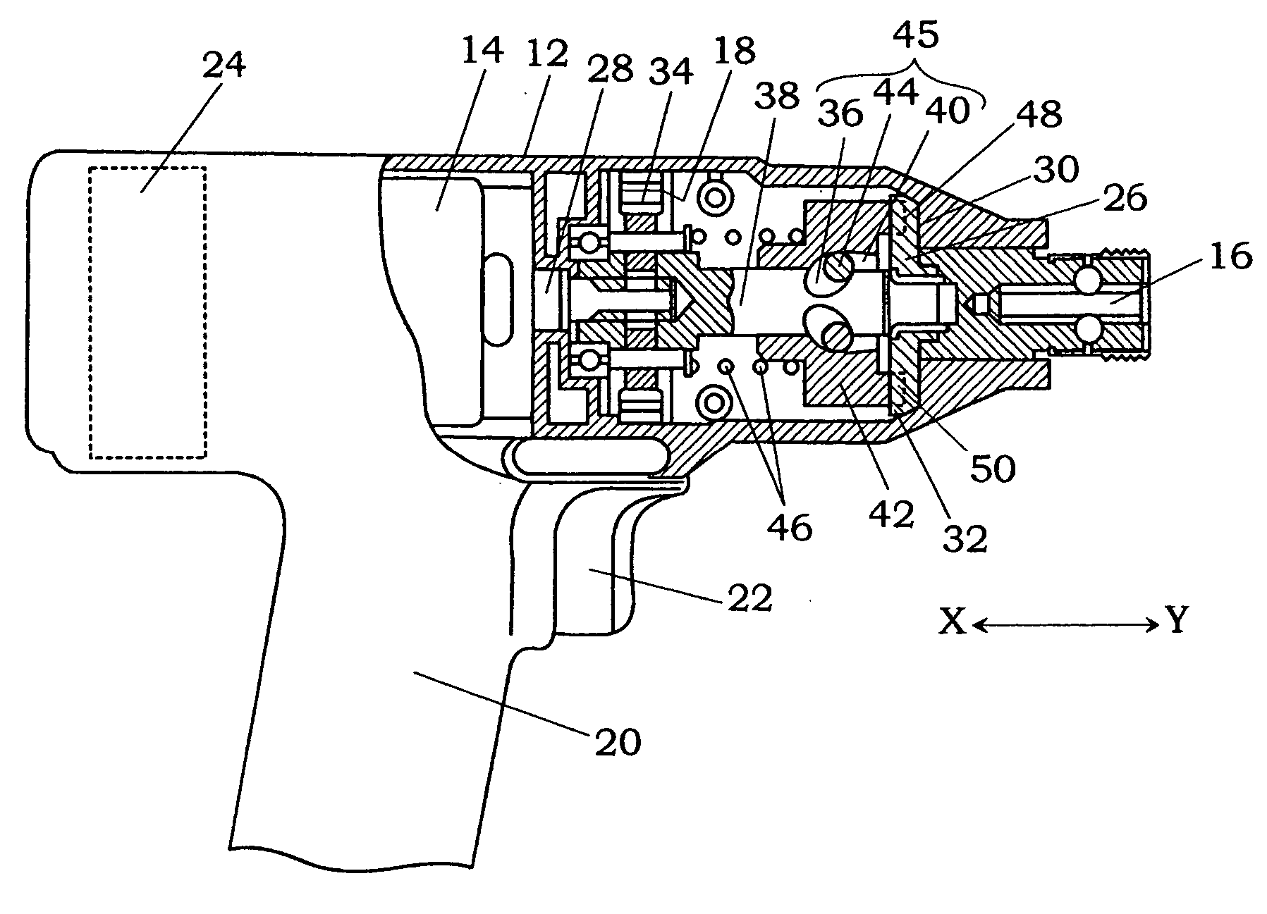
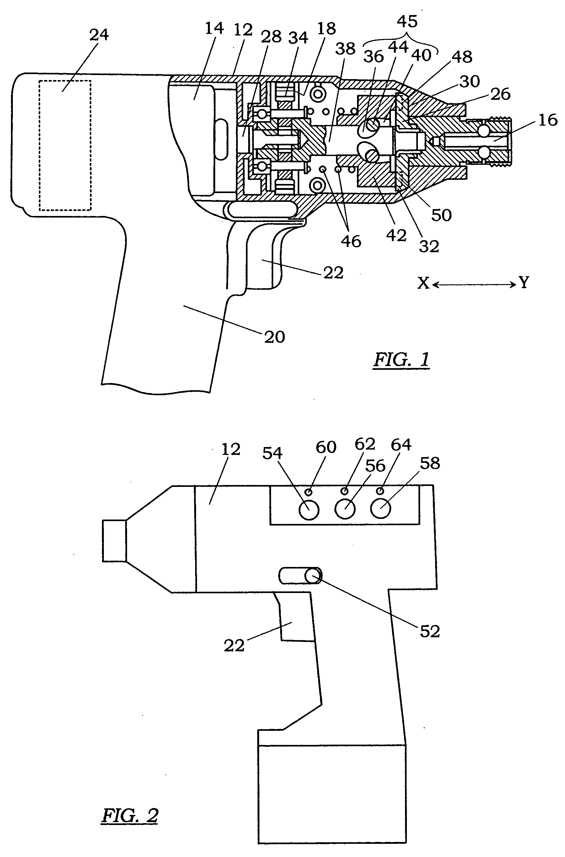
[0034] As shown in FIG. 1, the electric tool of the present embodiment is an impact rotary tool for performing operations of tightening and loosening fastening members such as bolts, nuts and screws. This electric tool comprises a housing 12 having a grip 20 extending downwardly therefrom, a reversible motor 14 incorporated in the housing, output shaft 16 rotationally driven by the motor, power transmission device 18 for transmitting a rotational force of the motor to the output shaft, and a controller 24 electrically connected to the reversible motor through a required interface circuit.

[0035] The motor 14 can be activated by a rechargeable battery (not shown) built in the housing 12. By inverting the polarity of a voltage applied to the motor, a rotary shaft of the motor is allowed to rotate in either forward or reverse direction. One end of...


PUM


Abstract

An electric tool having the capability of achieving a high working efficiency is provided. This tool comprises an output shaft rotated by reversible motor, a rotational-direction switch for switching a rotational direction of the output shaft in either forward or reverse direction, first memory for storing a plurality of operation modes of the output shaft with respect to one of the forward and reverse directions, operation-mode switch for selecting one from the operation modes, second memory for temporarily storing an operation mode selected by the operation-mode switch in a use of the electric tool at the one of the forward and reverse directions; and a controller for automatically setting the electric tool in the operation mode stored in the second memory in the next use of the electric tool at the one of the forward and reverse directions.

Description

BACKGROUND OF THE INVENTION [0001] 1. Field of the Invention [0002] The present invention relates to an electric tool with operation modes for providing different outputs to an object, and particularly the electric tool for applying a rotational force to the object such as bolts, nuts and screws through an output shaft driven by a reversible motor. [0003] 2. Disclosure of the Prior Art [0004] To carry out operations of tightening a fastening member such as a bolt, nut or a screw and loosening the fastening member, electric tools have been widely used. For example, an impact rotary driver is disclosed in Japanese Patent Early Publication No. 7-314342. According to this tool, when an output shaft is rotated in a forward direction by a reversible motor, the operation of tightening the fastening member can be performed. On the other hand, when the output shaft is rotated in the reverse direction, the operation of loosening the fastening member can be performed. In addition, the tool has...

Claims


Application Information

Patent Timeline
IPC IPC(8): B25B21/00B25B21/02B25B23/14B25D15/00
CPCB25B21/00B25B23/14B25B21/02B25F5/00
Inventor ARIMURA, TADASHIMIYAZAKI, HIROSHIITO, MASATOSHIOKAMURA, YUKIHIKOSAKAMOTO, KENJI
Owner MATSUSHITA ELECTRIC WORKS LTD
Why Eureka
Try Eureka