Demolition utility tool

a utility tool and demolition technology, applied in the field of demolition utility tools, can solve the problems of not only the cost of purchasing tools and modifying clothes, but the difficulty of firefighters advance fire hoses into the building to put out fire, and achieve the effect of convenient us

Inactive Publication Date: 2017-01-03
KAO CHIH CHEN
View PDF13 Cites 2 Cited by
  • Summary
  • Abstract
  • Description
  • Claims
  • Application Information

AI Technical Summary

Benefits of technology

[0006]In view of the fact that the conventional demolition tools mentioned above are single-function in nature and present problems to firefighters and rescue team members in terms of use, the inventor of the present invention incorporated years of practical experience into long-term research and experiment and finally succeeded in developing a demolition utility tool which is easy to use and is adaptive to different demolition operations.
[0007]It is an objective of the present invention to provide a demolition utility tool which includes a handle, a first tool portion, and a second tool portion. The handle is bar-shaped and is provided with the first tool portion and the second tool portion at two ends respectively. The first tool portion is formed with a gas shut-off feature engageable with a gas valve switch (e.g., a gas valve switch for controlling the supply of gas as a fuel) so that a user holding the handle can rotate and thereby turn off the gas valve switch. One side of the first tool portion is provided with an axe blade for chopping or breaking apart an object (e.g., a tree, wall, or door panel), and a corresponding side of the first tool portion is provided with a pike for cutting into an object (e.g., a tree or floor) by a striking action. The second tool portion is U-shaped and is provided at the end of the handle that is opposite the first tool portion. The second tool portion is configured to engage with a toothed locking element (e.g., a nut or bolt) so that a user can rotate the locking element with ease while holding the handle. Therefore, instead of carrying a good number of demolition tools around, one only has to bring the demolition utility tool with them in order to perform in a firefighting or demolition operation the chopping, cutting, or removing action required for each task on hand. Consequently, not only can the fighting or demolition operation be executed with great ease, but also the executor's safety is substantially enhanced.

Problems solved by technology

Closed doors and windows also hinder evacuation and make it difficult for firefighters to advance fire hoses into a building to put out fire.
However, the ways in which the demolition operations are performed give rise to various problems.
Consequently, not only are costs incurred for purchasing the tools and modifying the clothes, but also the firefighter may be inconvenienced by the tools carried.
Second, the total weight of the tools can be considerable and will add to the already heavy burden on a firefighter.
As firefighters tend to run in order to save time, the extra weight of the tools is very likely to accelerate the consumption of physical energy or even lead to premature fatigue, which will in turn delay the firefighting or rescue operation, if not putting the firefighters themselves in danger.
Last but not least, a firefighter carrying several tools with him must choose the right tool for the type of demolition operation on hand (e.g., to destroy a door or window, to knock down a wood panel or wall, or to unfasten a bolt or screw), and yet choosing the right tool can be time-consuming or difficult if the firefighter's vision is compromised by smoke or darkness at the site.
Hence, it is an important issue in the demolition tool industry to improve the existing products so that firefighters and rescue team members can carry fewer tools with them but are still capable of effectively performing various demolition operations and saving people or objects from danger as quickly as possible.

Method used


Image

  • Demolition utility tool
  • Demolition utility tool
  • Demolition utility tool

Examples


Embodiment Construction

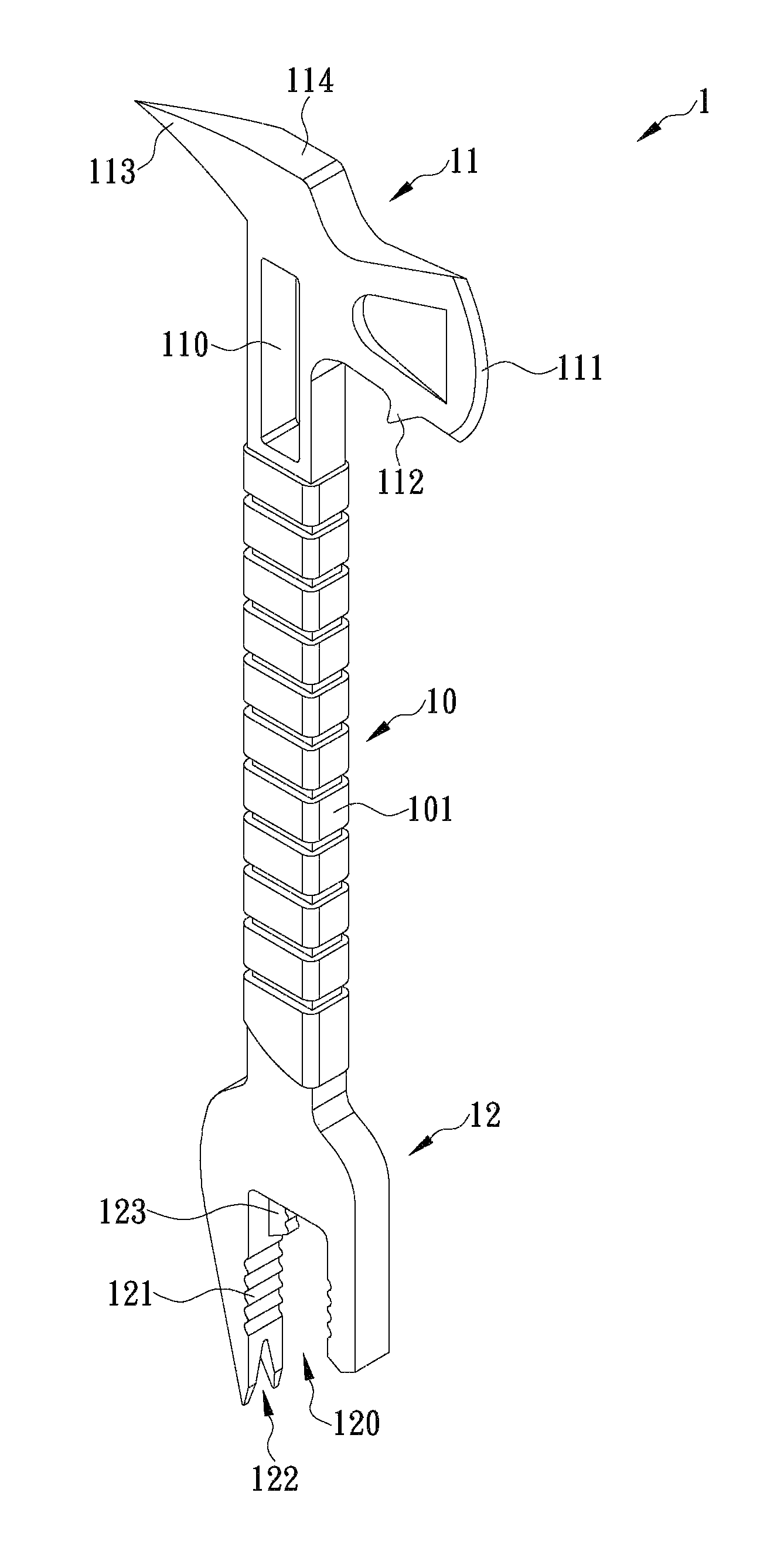
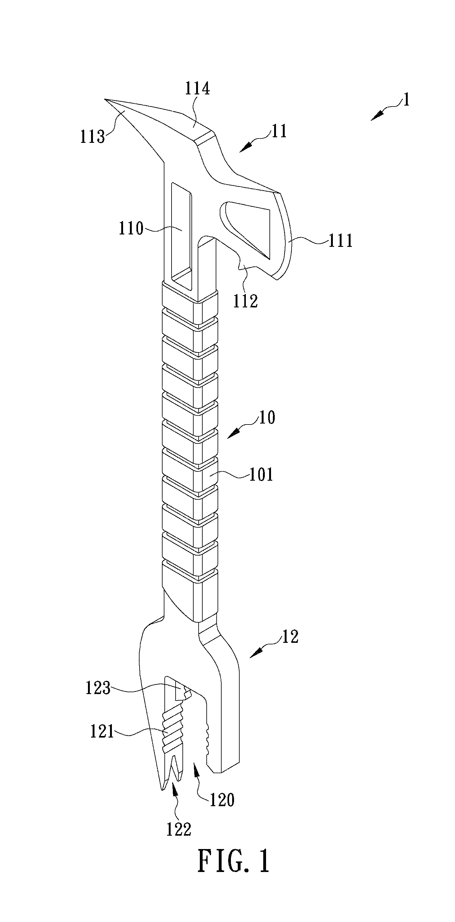
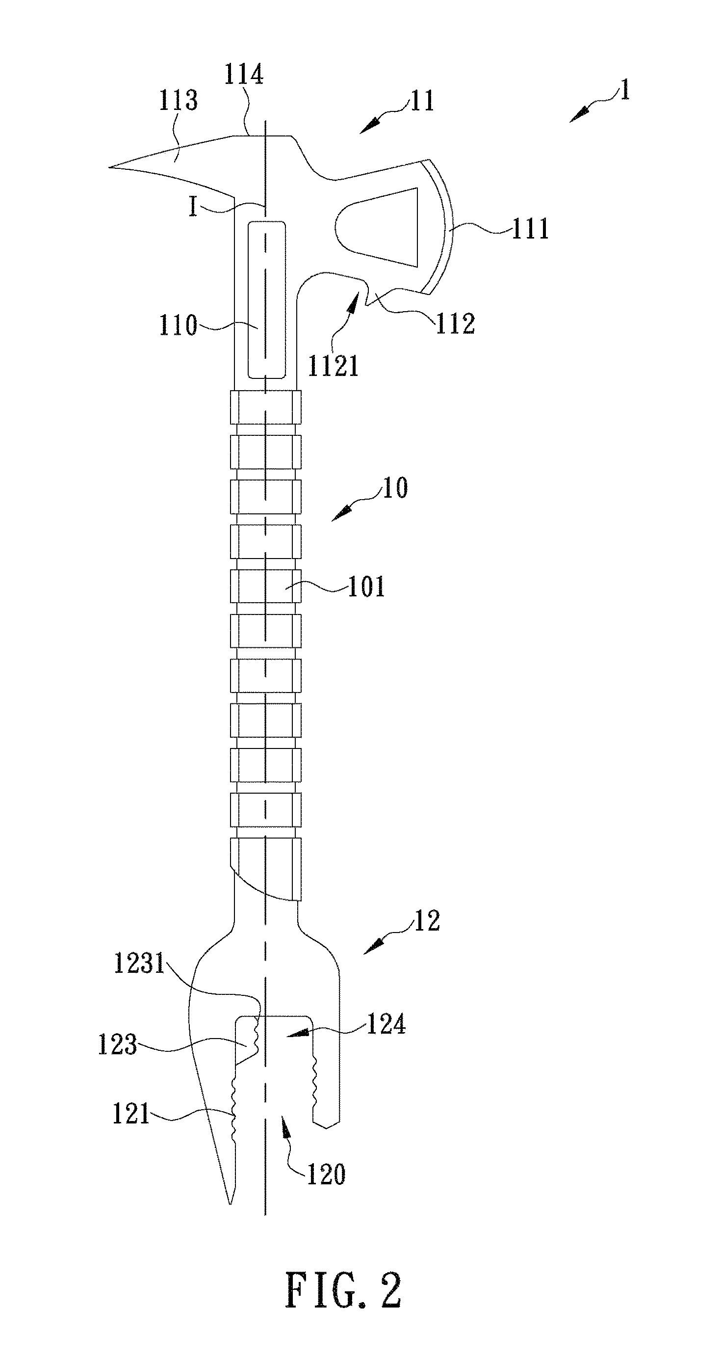
[0015]The present invention provides a demolition utility tool 1, whose overall structure is clearly shown in the different views of FIGS. 1˜3. In this embodiment, the demolition utility tool 1 includes a handle 10, a first tool portion 11, and a second tool portion 12. The handle 10 is bar-shaped and has two ends respectively provided with the first tool portion 11 and the second tool portion 12 so that a user can use the first tool portion 11 or the second tool portion 12 for demolition while holding the handle 10. In this embodiment, the handle 10, the first tool portion 11, and the second tool portion 12 are integrally formed. In other embodiments of the present invention, however, the first tool portion 11 and the second tool portion 12 can be mounted to the handle 10 by various mounting methods such as by locking, threaded connection, mutual engagement, etc.

[0016]With continued reference to FIGS. 1˜3, the outer surface of the handle 10 is covered with at least one anti-slip la...


PUM


Abstract

The present invention is to provide a demolition utility tool which includes a bar-shaped handle provided with a first tool portion and a second tool portion at two ends thereof, respectively. The first tool portion is formed with a gas shut-off feature for rotating and thereby turning off a gas valve switch, and has one side provided with an axe blade for chopping or breaking apart an object and another side provided with a pike for cutting into an object by a striking action. The second tool portion is U-shaped and configured to rotate a toothed locking element with ease while holding the handle. Therefore, instead of carrying a good number of demolition tools around, a firefighter only needs to bring the demolition utility tool for performing all kinds of demolition operations while in firefighting.

Description

FIELD OF THE INVENTION[0001]The present invention relates to a demolition utility tool, more particularly to a demolition utility tool being used by a firefighter for performing all kinds of demolition operations while in firefighting.BACKGROUND OF THE INVENTION[0002]According to statistics, death in a fire results far more frequently from choking or suffocation than from burning. The main reason for this lies in the fact that fire tends to break out at night or while people are asleep, during which time the doors and windows of the fire scene are often shut and therefore keep the heavy smoke from dissipating. Closed doors and windows also hinder evacuation and make it difficult for firefighters to advance fire hoses into a building to put out fire. As a result, firefighters or rescue team members must break the closed doors or windows with axes or other tools to enable water application to the interior of the building or help those trapped in the building to escape.[0003]In order n...

Claims


Application Information

Patent Timeline
Patent Type & Authority Patents(United States)
IPC IPC(8): A62B3/00B25F1/00
CPCA62B3/005B25F1/006
Inventor KAO, CHIH-CHEN
Owner KAO CHIH CHEN
Why Eureka
Try Eureka