Non-contact passive ranging system

a passive ranging and non-contact technology, applied in the field of distance measuring systems, can solve the problems of high cost, high power consumption, complex systems, etc., and achieve the effect of easy calculation of distance to the object and easy configuration to operate in different environments

Active Publication Date: 2009-06-04
CHARLES STARK DRAPER LABORATORY
View PDF5 Cites 2 Cited by
  • Summary
  • Abstract
  • Description
  • Claims
  • Application Information

AI Technical Summary

Benefits of technology

[0009]It is a further object of this invention to provide such a ranging system which is readily configurable to operate in different environments, for example in robotics, in vehicle based systems, and in portable navigation systems such as helmet or head mounted systems.
[0010]It is a further object of this invention to provide such a ranging system which is readily extensible to provide complete motion data.
[0011]The subject invention results at least in part from the realization that a viable non-contact passive ranging system, in one example, employs optical motion sensors configured so one is further away from an object than the other in which case the object will, to the sensors, appear to move at two different rates. Since the position of the two sensors is known, their outputs enable a processor to readily calculate the distance to the object. By extension, additional pairs of motion sensors allow the processor to fully calculate the motion of any platform the sensors are attached to.

Problems solved by technology

Systems such as sonar, lidar, radar, and the like involve active emission of energy from a sensor to the object and thus such systems are often complex, expensive, and power intensive.
The processing requirements underlying such systems are also typically intensive.
Also, many prior systems may be fairly slow to acquire range information.

Method used


Image

  • Non-contact passive ranging system
  • Non-contact passive ranging system
  • Non-contact passive ranging system

Examples


Embodiment Construction

[0024]Aside from the preferred embodiment or embodiments disclosed below, this invention is capable of other embodiments and of being practiced or being carried out in various ways. Thus, it is to be understood that the invention is not limited in its application to the details of construction and the arrangements of components set forth in the following description or illustrated in the drawings. If only one embodiment is described herein, the claims hereof are not to be limited to that embodiment. Moreover, the claims hereof are not to be read restrictively unless there is clear and convincing evidence manifesting a certain exclusion, restriction, or disclaimer.

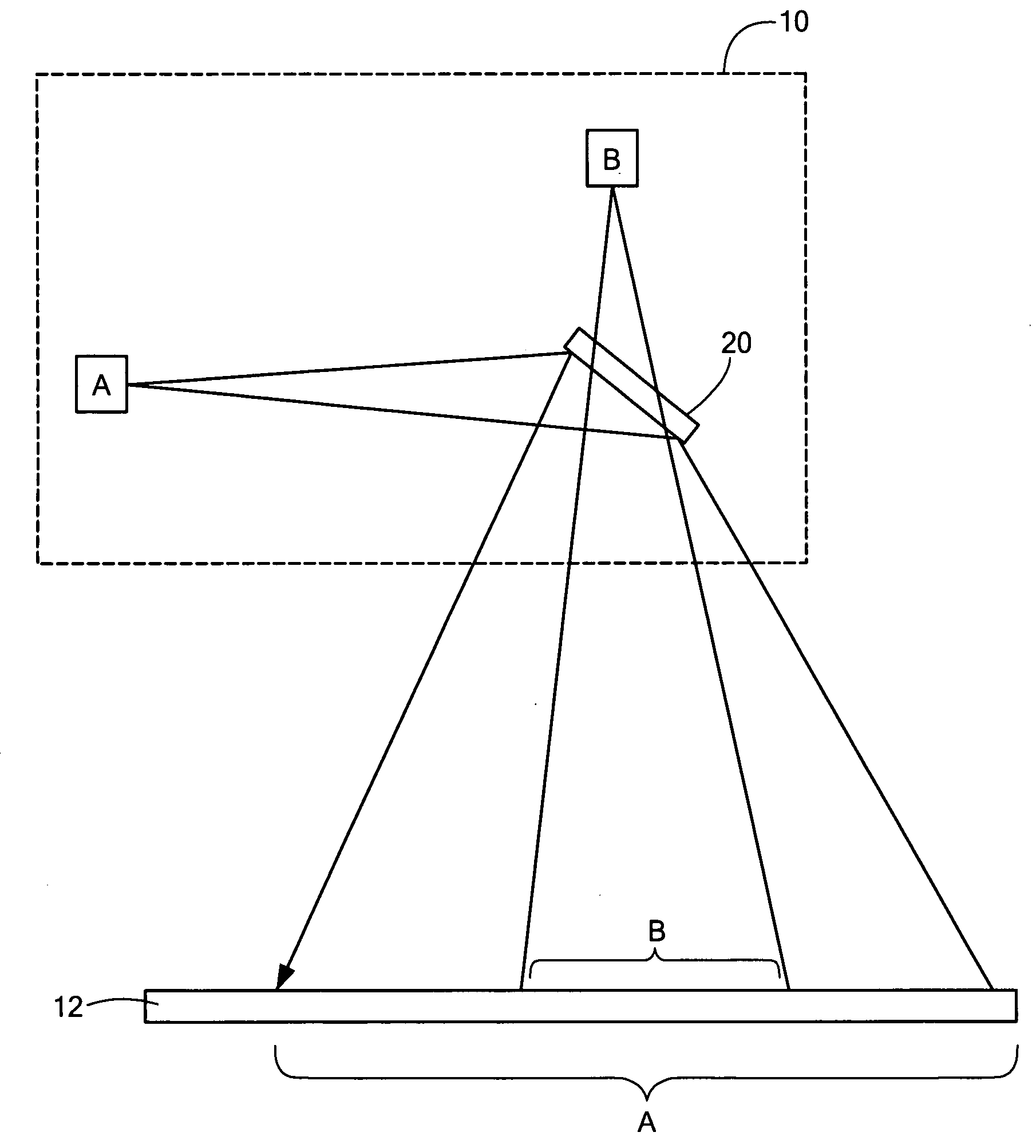
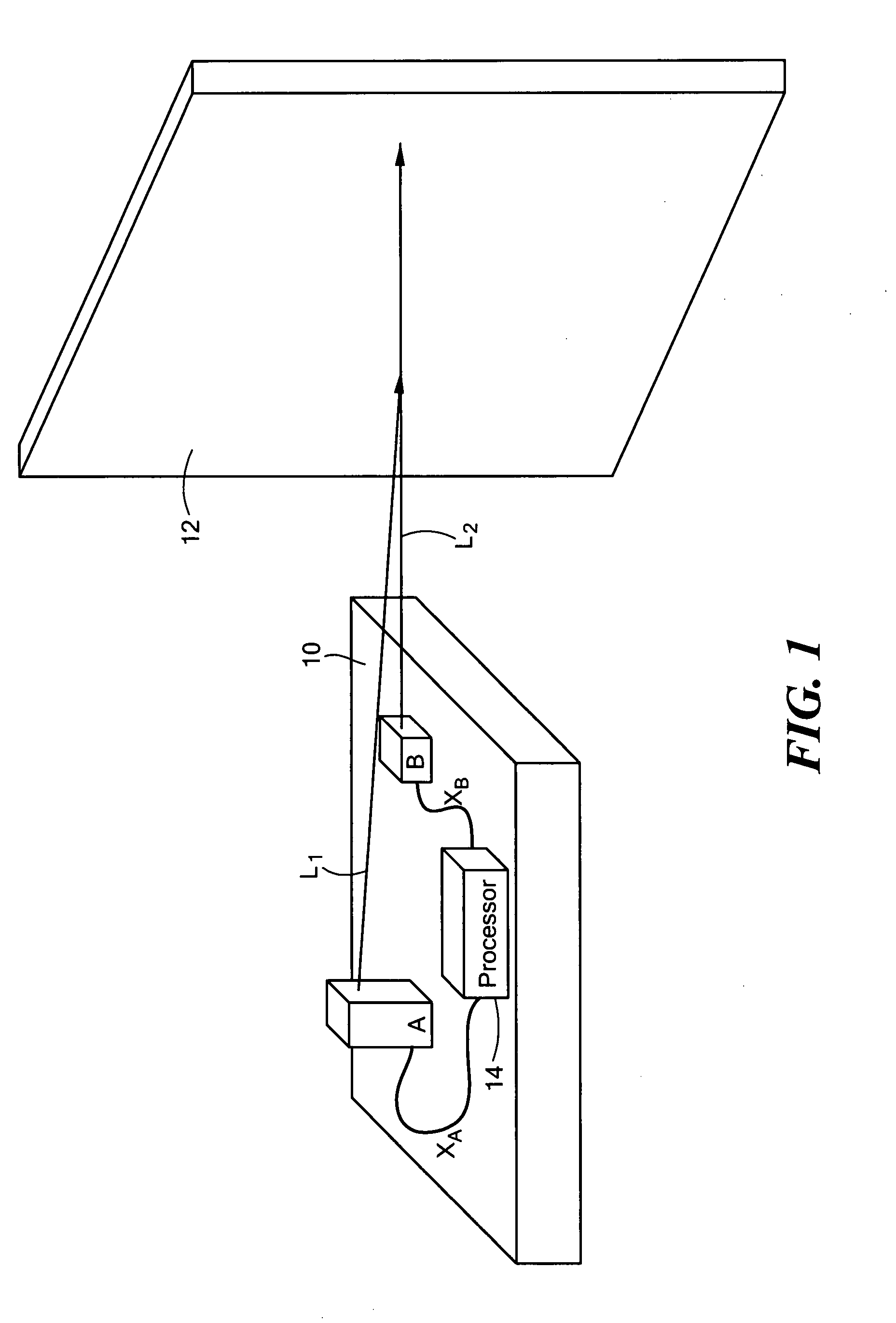
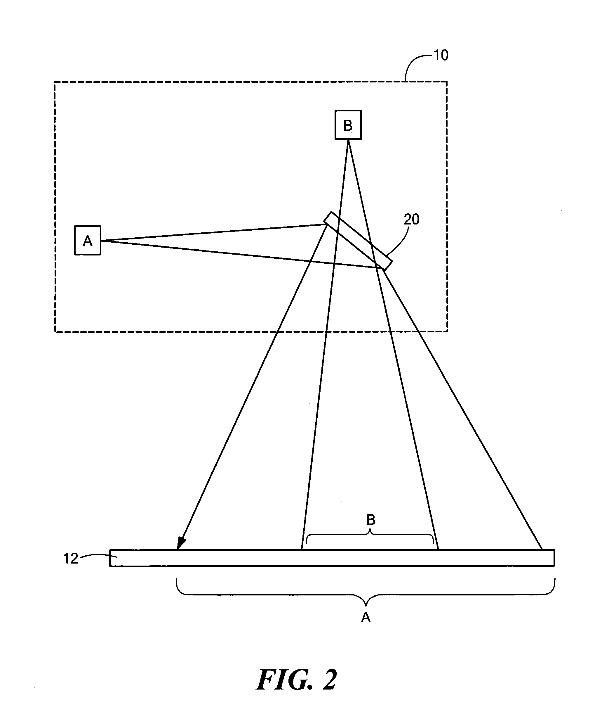
[0025]FIG. 1 schematically depicts an example of a non-contact passive ranging system in accordance with the subject invention. A passive imager B is mounted on platform 10 (a robot or a piece of machinery, for example) and is focused on object 12 (a wall, for example). Imager A is also located on platform 10 and focused on...


PUM


Abstract

A non-contact passive ranging system wherein a first imager on a platform is focused on a first object and a second imager on the platform is also focused on the first object. The optical path from the first object to the first imager is configured to be shorter than the optical path from the object to the second imager. Processing circuitry is responsive to an output of the first imager and an output of the second imager as relative motion is provided between the platform and the first object and is configured to calculate the distance from the platform to the object.

Description

FIELD OF THE INVENTION[0001]This subject invention relates to distance measuring systems.BACKGROUND OF THE INVENTION[0002]Numerous distance measuring systems are known in the art and, by extension, so are systems which are able to resolve the motion of an object. Systems such as sonar, lidar, radar, and the like involve active emission of energy from a sensor to the object and thus such systems are often complex, expensive, and power intensive. The processing requirements underlying such systems are also typically intensive. Also, many prior systems may be fairly slow to acquire range information.[0003]In fields such as robotics and portable navigation systems, fast, inexpensive, and low power ranging systems are desired.SUMMARY OF THE INVENTION[0004]It is therefore an object of this invention to provide a non-contact ranging system which is passive.[0005]It is a further object of this invention to provide such a ranging system which does not involve intensive processing requirement...

Claims


Application Information

Patent Timeline
Patent Type & Authority Applications(United States)
IPC IPC(8): G06K9/00
CPCG01S11/12G01C3/08
Inventor RASMUSSEN, SCOTTZERVOGLOS, NICHOLASDEBITETTO, PAUL
Owner CHARLES STARK DRAPER LABORATORY
Why Eureka
Try Eureka