Method for manufacturing magnetic recording medium

a manufacturing method and magnetic recording technology, applied in the field of magnetic recording medium manufacturing, can solve the problems of insufficient flattening of the surface of the recording layer and the non-magnetic material, the approaching limit of the improvement of the areal density by conventional improvement methods, and the inability to achieve the effect of improving the areal density

Inactive Publication Date: 2005-03-03
TDK CORPARATION
View PDF6 Cites 8 Cited by
  • Summary
  • Abstract
  • Description
  • Claims
  • Application Information

AI Technical Summary

Benefits of technology

[0011] In view of the foregoing problems, various exemplary embodiments of this invention provide a method for manufacturing a magnetic recording medium, by which the magnetic

Problems solved by technology

However, problems such as the limitations of sophisticating of a head processing, a side fringe and crosstalk caused by the extent of a magnetic field have become conspicuous, and the improvement of the areal density by use of conventional improving methods is approaching its limits.
When the film thickness of the non-magnetic material is thin, however, the recessed portion of the concavo-convex pattern is not completely filled with the non-magnetic material, so that there are cases that the surfaces of the recording layer and the non-magnetic material cannot be flattened sufficiently.
Even if the recessed portions of the concavo-convex pattern are completely filled with the non-magnetic material, when the film thickness of the non-magnetic

Method used


Image

  • Method for manufacturing magnetic recording medium
  • Method for manufacturing magnetic recording medium
  • Method for manufacturing magnetic recording medium

Examples


example 1

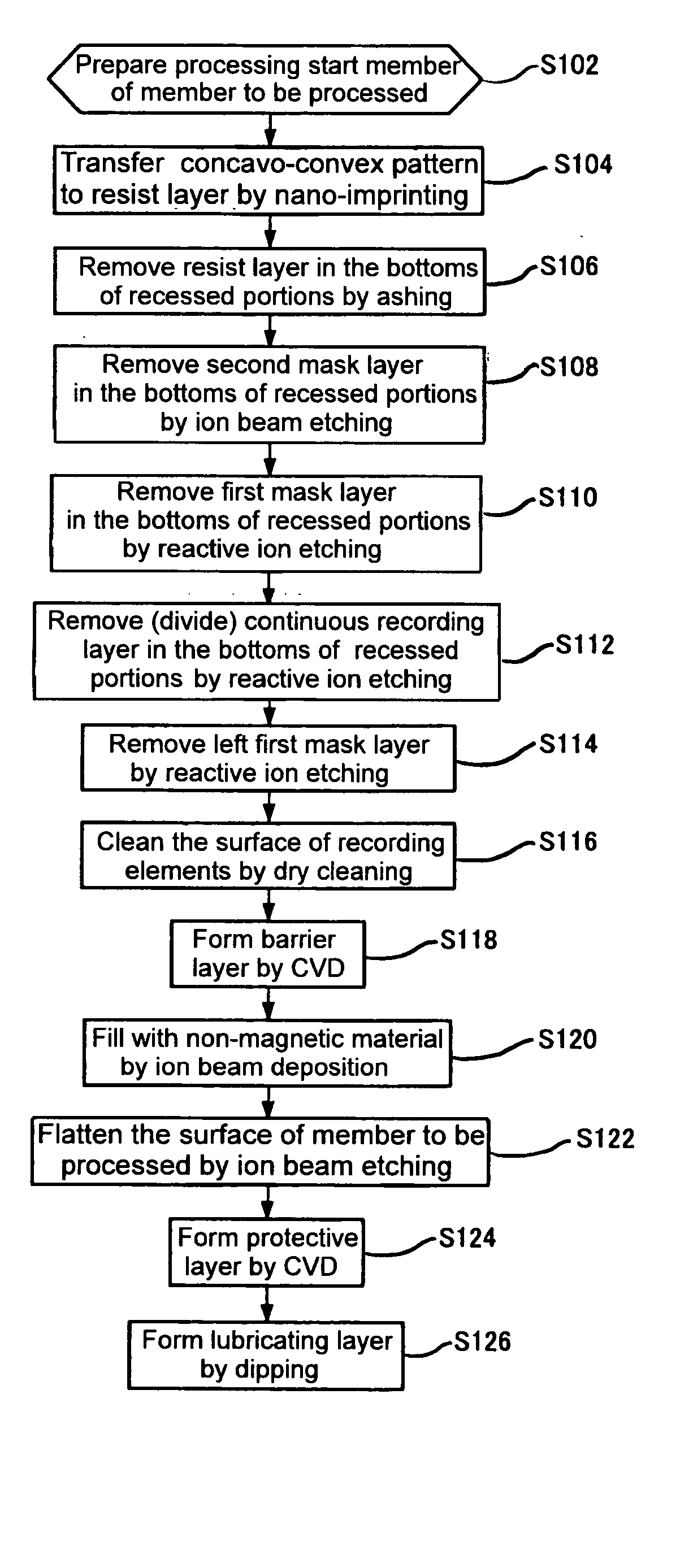
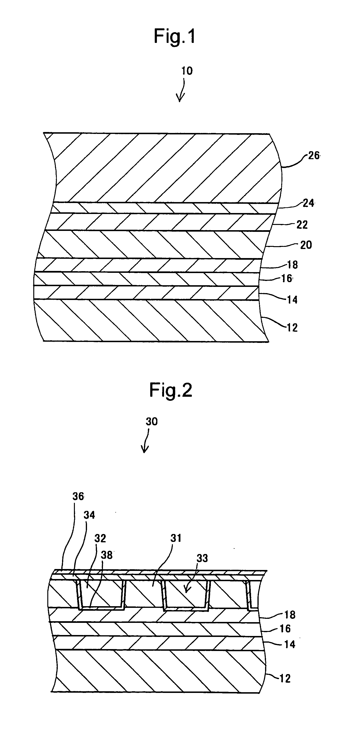
[0090] According to the foregoing exemplary embodiment, four members to be processed 10 were processed into a concavo-convex pattern, and a continuous recording layer 20 of each of them was divided into many recording elements 31. In the concavo-convex pattern, as shown in a table 1, a track pitch (the distance between projections of the concavo-convex pattern=the distance between recessed portions) was 300 nm, the width of the recording element was 230 nm, the width of the recessed portion was 70 nm, and a step height (a height of the recording element) was 45 nm.

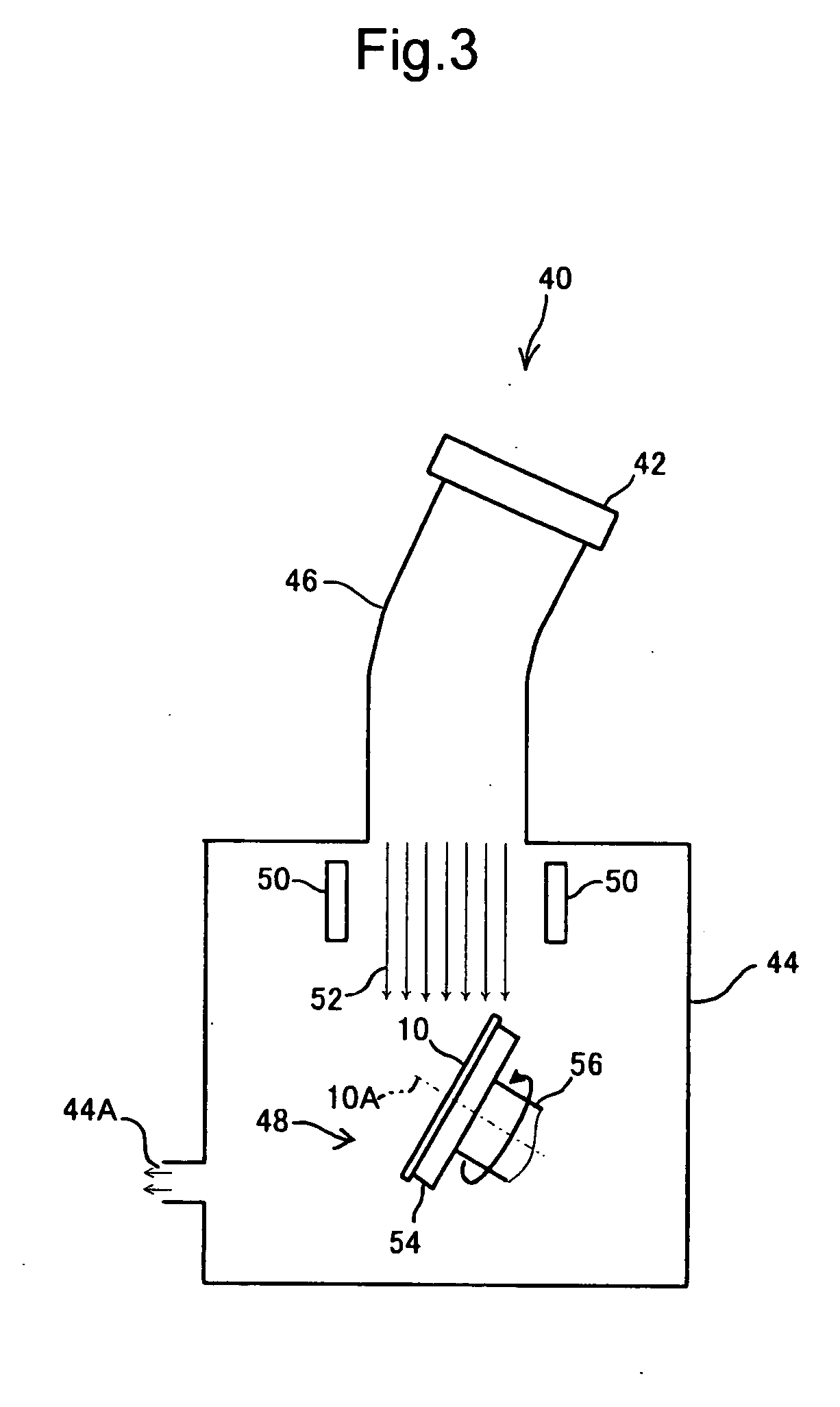
[0091] Then, a layer of SiO2 was deposited in a thickness of approximately 100 nm while rotating each member to be processed 10 at a rotational speed of approximately 18 rpm by use of the ion beam deposition device 40, to fill the recessed portions-between the recording elements 31 with SiO2. At this time, each member to be processed 10 was held in such a manner that the application angle of the particles of the non-magne...

example 2

[0097] Comparing with the example 1, four members to be processed 10 were processed while changing a concavo-convex pattern as shown in the table 1, and a continuous recording layer 20 thereof was divided into many recording elements 31. In the concavo-convex pattern, the track pitch was 200 nm, the width of the recording element was 150 nm, and the width of a recess portion was 50 nm. The other conditions were the same as those of the example 1.

[0098] A curve with a symbol B′ of FIG. 18 indicates relations between the application angle of the particles of the non-magnetic material in the non-magnetic material filling process and an average step height in the flattened surface of each member to be processed 10.

example 3

[0099] Comparing with the examples 1 and 2, four members to be processed 10 were processed while changing the track pitch to 150 nm, the width of the recording element to 110 nm, the width of the recess portion to 40 nm, and the step height to 35 nm. Then, a continuous recording layer 20 was divided into many recording elements 31. The other conditions were the same as those of the example 1.

[0100] In FIG. 15, a curve with a symbol C indicates relations between the application angle of the particles of the non-magnetic material in the non-magnetic material filling process and an average step height in the surface of the non-magnetic material 32 deposited on each member to be processed 10.

[0101] A curve with a symbol C′ of FIG. 18 indicates relations between the application angle of the particles of the non-magnetic material in the non-magnetic material filling process and an average step height in the flattened surface of each member to be processed 10.


PUM


Abstract

A method for manufacturing a magnetic recording medium is provided, by which the magnetic recording medium having a recording layer formed into a predetermined concavo-convex pattern and an adequately flat surface can be efficiently and certainly manufactured. Particles of a non-magnetic material are applied to a member to be processed from a direction relatively inclined with respect to a normal to the surface of the member to be processed. Also, the member to be processed is rotated around a central axis which is inclined with respect to an application direction of the particles of the non-magnetic material, to fill recessed portions of the concavo-convex pattern with the non-magnetic material.

Description

BACKGROUND OF THE INVENTION [0001] 1. Field of the Invention [0002] The present invention relates to a method for manufacturing a magnetic recording medium. [0003] 2. Description of the Related Art [0004] Conventionally, in a magnetic recording medium such as a hard disc the areal density thereof has been increased remarkably by various technical improving methods such as,making magnetic particles composing a recording layer finer, changing of materials, sophisticating of a head processing. Further improvement of the areal density is expected in the future. [0005] However, problems such as the limitations of sophisticating of a head processing, a side fringe and crosstalk caused by the extent of a magnetic field have become conspicuous, and the improvement of the areal density by use of conventional improving methods is approaching its limits. Accordingly, a discrete track type magnetic recording medium has been proposed as a candidate for a magnetic recording medium which can reali...

Claims


Application Information

Patent Timeline
IPC IPC(8): G11B5/65G11B5/74G11B5/84G11B5/855
CPCB82Y10/00G11B5/855G11B5/743G11B5/74
Inventor SUWA, TAKAHIROHATTORI, KAZUHIROOKAWA, SHUICHI
Owner TDK CORPARATION
Why Eureka
Try Eureka