Near field electromagnetic positioning system and method

a positioning system and electromagnetic technology, applied in the direction of instruments, transmission, reradiation, etc., can solve the problems of affecting the ideal planar uniform behavior, affecting the accuracy of position information, and elusive affordable position information,

Active Publication Date: 2005-03-03
GAN CORP
View PDF99 Cites 158 Cited by
  • Summary
  • Abstract
  • Description
  • Claims
  • Application Information

AI Technical Summary

Problems solved by technology

Accurate, affordable position information however has been elusive.
A principal source of difficulty arises from the fact that typical environments are not ideal.
Outdoors, typical environments contain objects such as trees, hills, buildings, cars and such that disrupt ideal planar uniform behavior.
In both cases, real world environments have complicated behaviors that defy exact reliable predictions.
However, positioning based on relative signal strength is notoriously inaccurate.
This often makes it uneconomical to achieve high precision positioning.

Method used


Image

  • Near field electromagnetic positioning system and method
  • Near field electromagnetic positioning system and method
  • Near field electromagnetic positioning system and method

Examples


Embodiment Construction

The present invention will now be described more fully in detail with reference to the accompanying drawings, in which the preferred embodiments of the invention are shown. This invention should not, however, be construed as limited to the embodiments set forth herein; rather, they are provided so that this disclosure will be thorough and complete and will fully convey the scope of the invention to those skilled in art.

Overview of the Invention

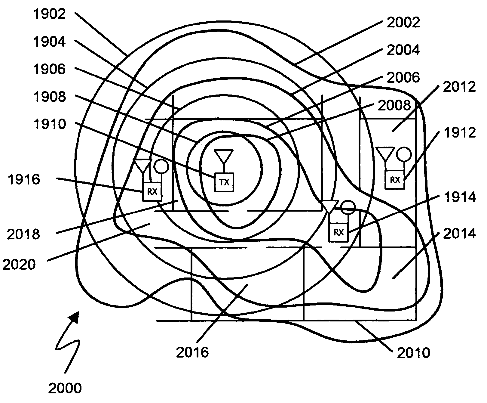
The present invention is directed to a system and method for determining position using a near field electromagnetic ranging system. The system and method may include the use of calibration information provided by field measurements. Near field electromagnetic ranging was first fully described in applicant's co-pending “System and Method for Near Field Electromagnetic Ranging,” Filed Jan. 31, 2003, Ser. No. 10 / 355,612, published as Pub. No. US 2004 / 0032363 A1, to Schantz et al, This document has been incorporated herein by reference.

An ...


PUM


Abstract

A system and method for electromagnetic position determination utilizing a calibration process. For calibration, a transmitter is positioned at multiple locations in an area of interest and multiple receivers receive and record signal characteristics from the transmitter to generate a calibration data set. The unknown position of a transmitter may be determined by receiving signals from the transmitter by multiple receivers. A locator data set is generated based on the comparison between two received signal characteristics determined for each receiver. The locator data set is compared with the calibration data set to determine the unknown position. In one embodiment, the signal comparisons are the differences between electric and magnetic field phase. Further embodiments utilize signal amplitude differences. A reciprocal method utilizing a single receiver and multiple transmitter locations is disclosed. A further method is disclosed for determining position by utilizing signals available from existing installed wiring such as power wiring.

Description

BACKGROUND OF THE INVENTION 1. Field of the Invention The present invention relates generally to the measurement of position or location by means of electromagnetic signaling and more particularly to position measurement utilizing near field signals in conjunction with a calibration process. 2. Related Art Radio frequency (RF) techniques have been proposed to solve many ranging and position measuring problems in industry. For example, significant cost reduction is possible if inventories could be automatically tracked in a warehouse. Hospitals need to know the location of resources such as wheel chairs, gurneys, and diagnostic equipment for speedy retrieval when needed and for cost efficient operations. Hotels and resorts need to know the location of resources such as projectors, lawn mowers, golf carts, etc. Position information could inform a security system keeping track of inventories in a retail establishment and guarding against theft. Position information is critical to t...

Claims


Application Information

Patent Timeline
Patent Type & Authority Applications(United States)
IPC IPC(8): G01S19/19G01S5/00G01S5/14G01S11/06G01S13/75G01S19/11
CPCG01S5/0027G01S5/0081H04B5/0075G01S11/06G01S13/75G01S5/14
Inventor SCHANTZ, HANS GREGORYLANGFORD, DAVID WESLEY
Owner GAN CORP
Why Eureka
Try Eureka