
Imaging device and portable equipment

Inactive Publication Date: 2005-03-03
KONICA MINOLTA OPTO
View PDF6 Cites 9 Cited by
  • Summary
  • Abstract
  • Description
  • Claims
  • Application Information

AI Technical Summary

Benefits of technology

[0007] The present invention has been made in consideration of the problems of the prior art and an object of the invention is to provide an imaging device that is possible to conduct a focus adjustment with a high degree of accuracy due to high accurate fit between a hanger shaft and a hanger shaft hole of a lens frame.
[0015] In accordance with the invention, it is easy to strip a mold when molding the hanger shaft and the hanger shaft hole of the lens frame. Because of high accuracy of fit between the hanger shaft and the hanger shaft hole of the lens frame, it is also possible to conduct a focus adjustment with a high degree of accuracy. As the hanger shaft is integrally formed on the chassis, it has a good inclination accuracy.

Problems solved by technology

Imagers with high pixel densities, however, require focusing and thus require a drive unit for moving the lenses in a direction of an optical axis for the focusing.
Provision of such a drive unit involves a large camera unit and makes it difficult to install the unit in mobile phones and the like.
Especially, in a imaging device having an imaging unit having a side of not more than 10 mm, it is difficult to satisfy an inclination accuracy of the hanger shaft and a fit accuracy between the hanger shaft and the hanger shaft hole.

Method used


Image

  • Imaging device and portable equipment
  • Imaging device and portable equipment
  • Imaging device and portable equipment

Examples


Embodiment Construction

[0029] Hereinbelow, embodiments of the invention will be described with reference to the accompanying drawings.

Embodiment of Imaging Device

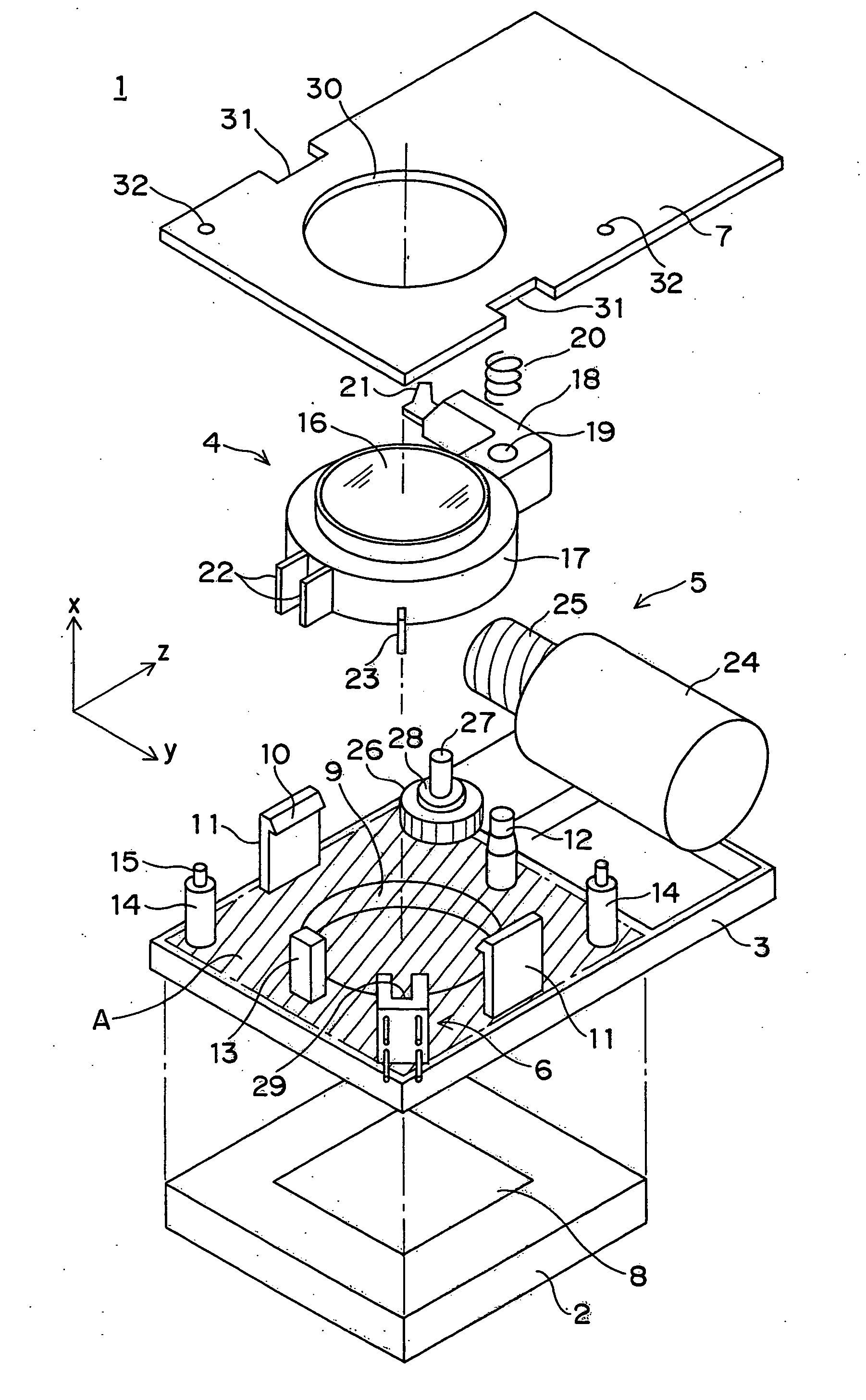
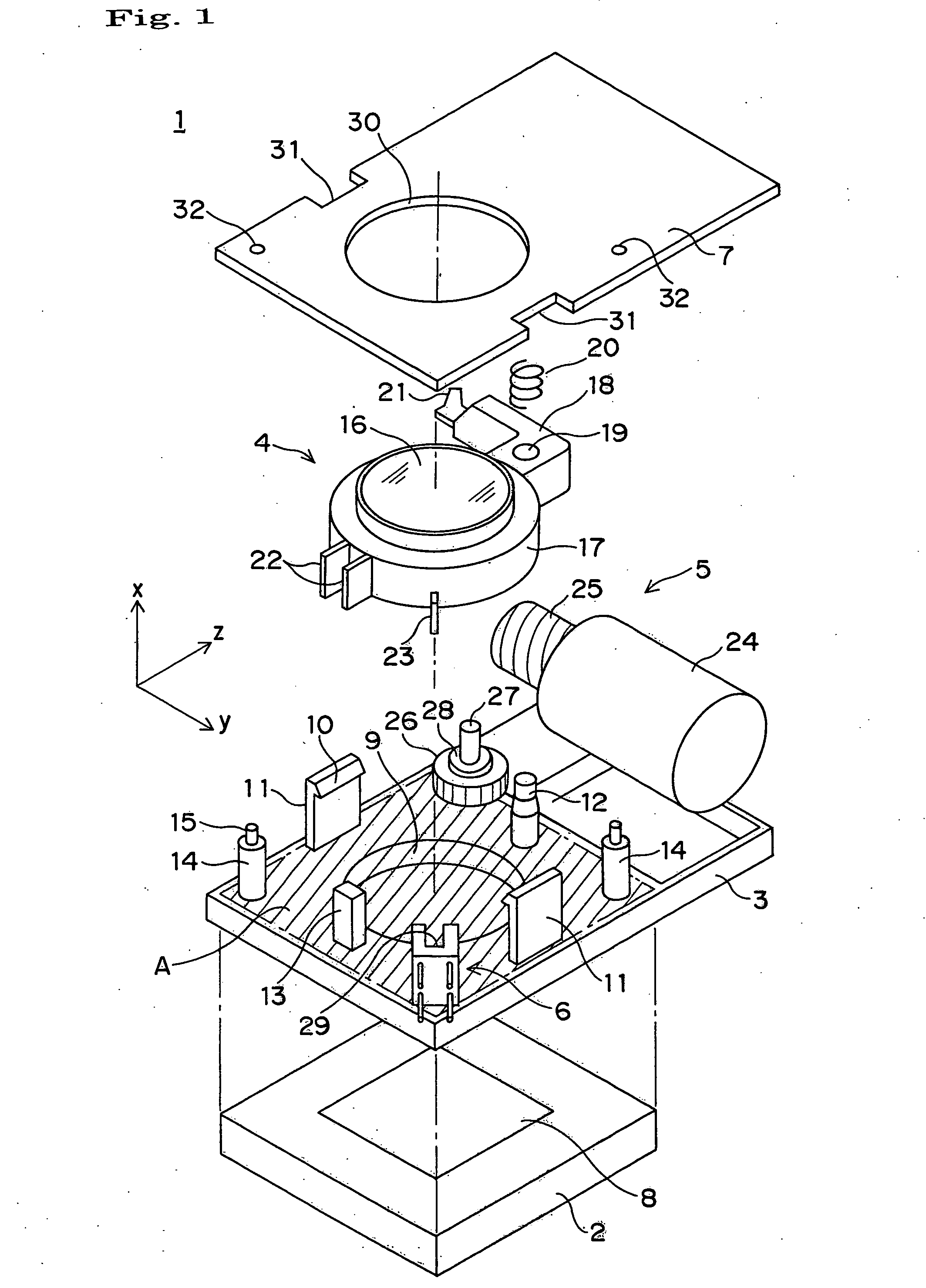
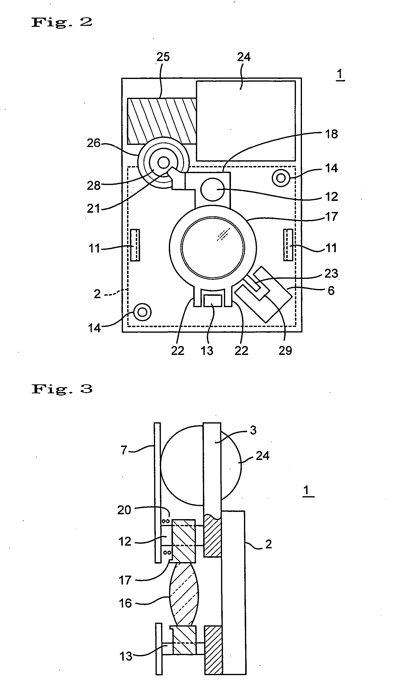
[0030]FIGS. 1 through 3 show an imaging device 1 in accordance with a first embodiment of the invention. The imaging device 1 is composed of an imaging unit 2, a chassis 3, an optical unit 4, a drive unit 5, a detector 6, and a cover 7.

[0031] The imaging unit 2 has a rectangular shape and includes a photoelectric converter 8 composed of, for example, a CCD sensor or a CMOS sensor at a center thereof. The imaging unit 2 is mounted on a control substrate not shown. Lengths of sides of the imaging unit 2 are on the order of 10 mm. The shape of the imaging unit 2 is not limited to such a rectangular one as in the embodiment but circular or other shapes may be employed.

[0032] The chassis 3 is a base on which the units of the imaging device 1 are to be mounted, and has a rectangular shape having sides substantially as long as those of the imaging u...


PUM


Abstract

The present invention provides an imaging device that is possible to conduct a focus adjustment with a high degree of accuracy due to high accurate fit between a hanger shaft and a hanger shaft hole of a lens frame. The imaging device 1 has an imaging unit 2, an optical unit 4 comprising a lens 16 and a lens frame 17 which supports the lens 16 and has a hanger shaft hole 19, a chassis 3 on which a hanger shaft 12 is integrally formed to fit into the hanger shaft hole 19, and a drive unit 5 for actuating the lens frame 17 of the optical unit 4 in an optical axis direction. The hanger shaft 12 has a plurality of diameters d1, d2 so that the chassis side of the hanger shaft 12 is largest and the side apart from the chassis 3 becomes small. The hanger shaft hole 19 has a plurality of diameters d3, d4 which fit to the hanger shaft 12.

Description

[0001] This application is based on an application No. 2003-306363 filed in Japan, the contents of which is hereby incorporated by reference. BACKGROUND OF THE INVENTION [0002] The present invention relates to an imaging device installed in portable equipment such as mobile phone, PHS (Personal Handy-phone System), PDA (Personal Digital Assistant), and mobile personal computer, surveillance camera, and the like. The present invention also relates to a portable equipment utilizing the imaging device. [0003] In recent years, mobile phones and the like having a camera installed therein have become pervasive. There has been a trend for imagers to have greater number of pixels in cameras installed in mobile phones, three hundred and ten thousand pixels has been common nowadays, and one million pixels has become commercially practical. As imaging units that include such imagers with high pixel densities, those with sizes not larger than 10 mm in length of one side (in rectangular shapes) ...

Claims


Application Information

Patent Timeline
IPC IPC(8): H04N5/225G02B7/04
CPCH04N5/2254H04N23/673H04N23/55
Inventor KUCHIMARU, TORU
Owner KONICA MINOLTA OPTO
Learn More