Scalable approach to large scale queuing through dynamic resource allocation

a resource allocation and large-scale technology, applied in the field of network management, can solve problems such as the inability to allocate physical queues, and achieve the effect of reducing the number of physical queues

Active Publication Date: 2005-03-03
CISCO TECH INC
View PDF35 Cites 12 Cited by
  • Summary
  • Abstract
  • Description
  • Claims
  • Application Information

AI Technical Summary

Benefits of technology

[0024] Yet other aspects of the invention provide a method of allocating queues in a network device. The method includes the following steps: determining a first number of packets that an ingress port of the network device can receive; and allocating a second number of physical queues for the ingress port, wherein the second number is less than or equal to the first number. According to some such aspects of the invention, the network device operates according to the Fibre Channel protocol and the determining step is based on a number of buffer-to-buffer credits granted by the ingress port.
[0025] The method may also include the following steps: identifying a category for each packet arriving at the ingress port; correlating the category to an existing physical queue; and storing packet information in the physical queue. The packet information may be control information such as destination information, source information, priority information, payload type information and / or payload size information. The method may include these additional steps: identifying a category for each packet arriving at the ingress port; and assigning the category to a physical queue, wherein the network device allocates a new physical queue only when there is no existing physical queue for the category.

Problems solved by technology

Because the flow control mechanisms (e.g., input buffering requirements) of Fibre Channel (“FC”) and other protocols place limitations on the number of incoming packets, the dynamic allocation methods of the present invention result in a sparse allocation of physical queues.

Method used


Image

  • Scalable approach to large scale queuing through dynamic resource allocation
  • Scalable approach to large scale queuing through dynamic resource allocation
  • Scalable approach to large scale queuing through dynamic resource allocation

Examples


Embodiment Construction

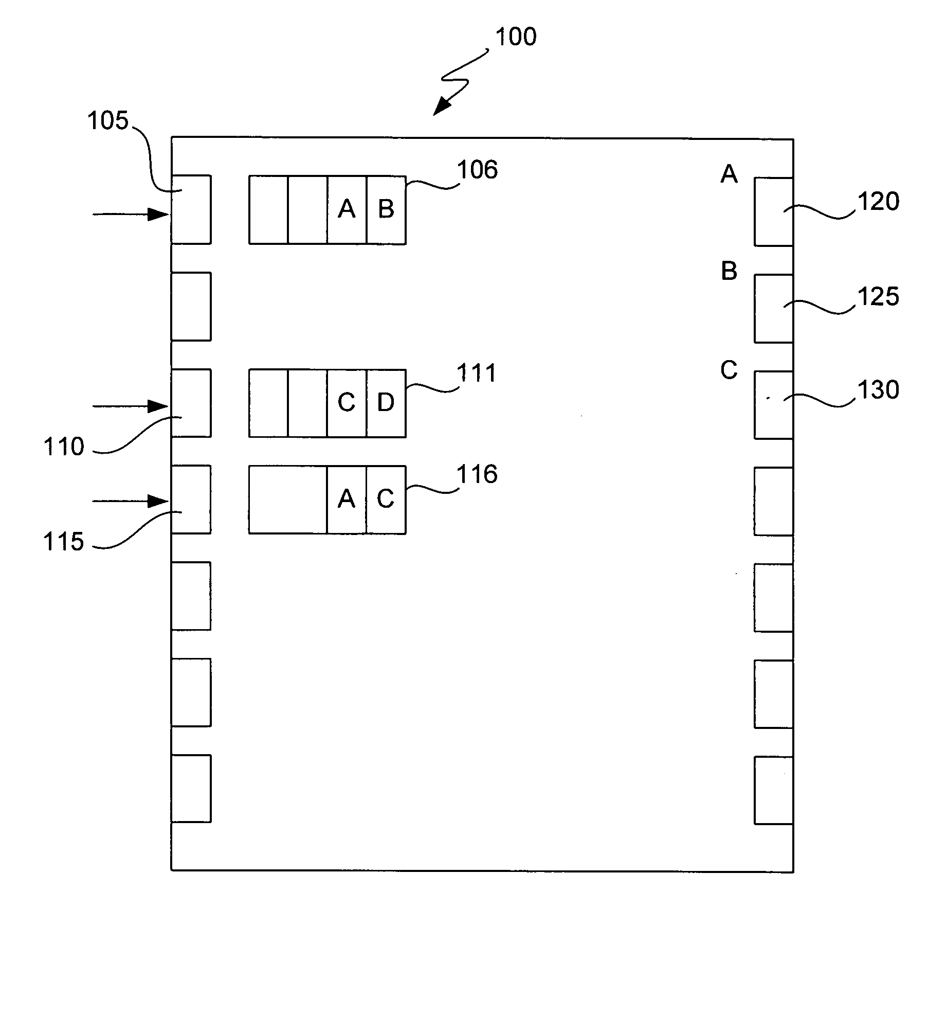
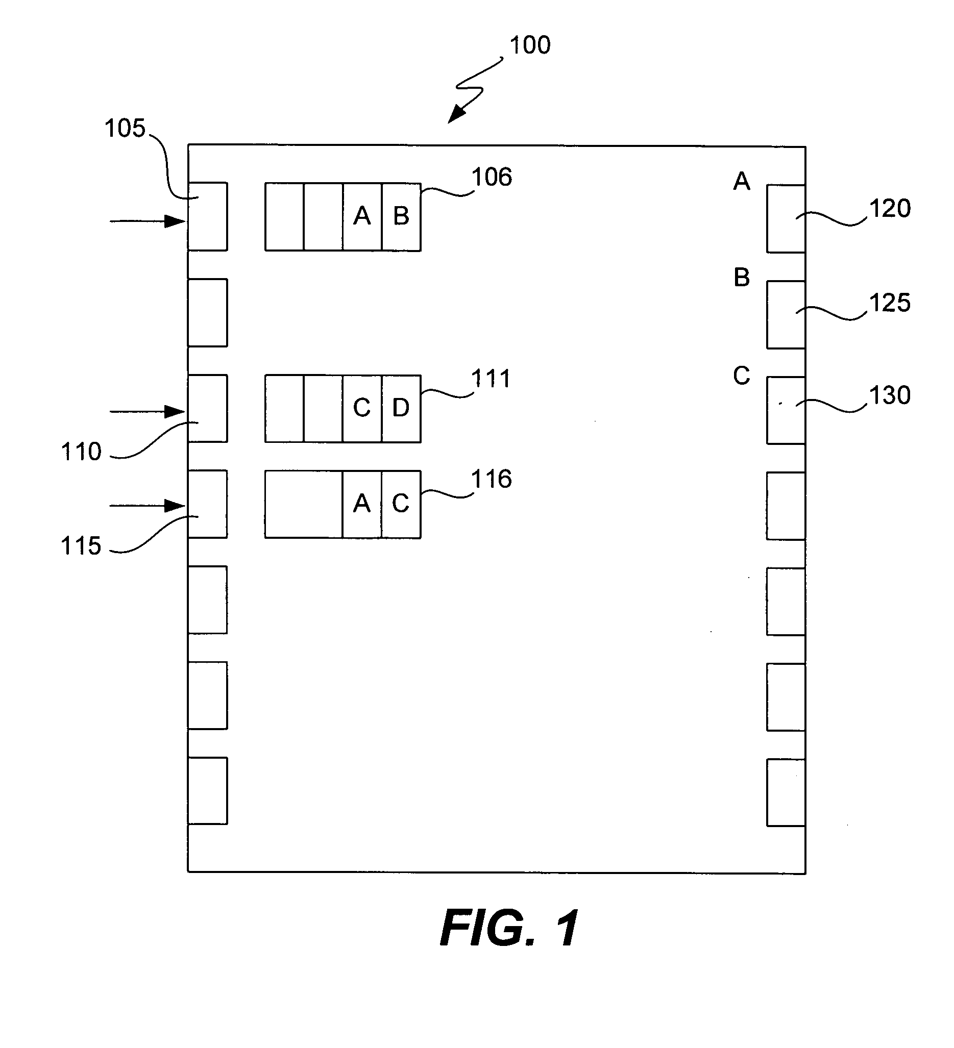
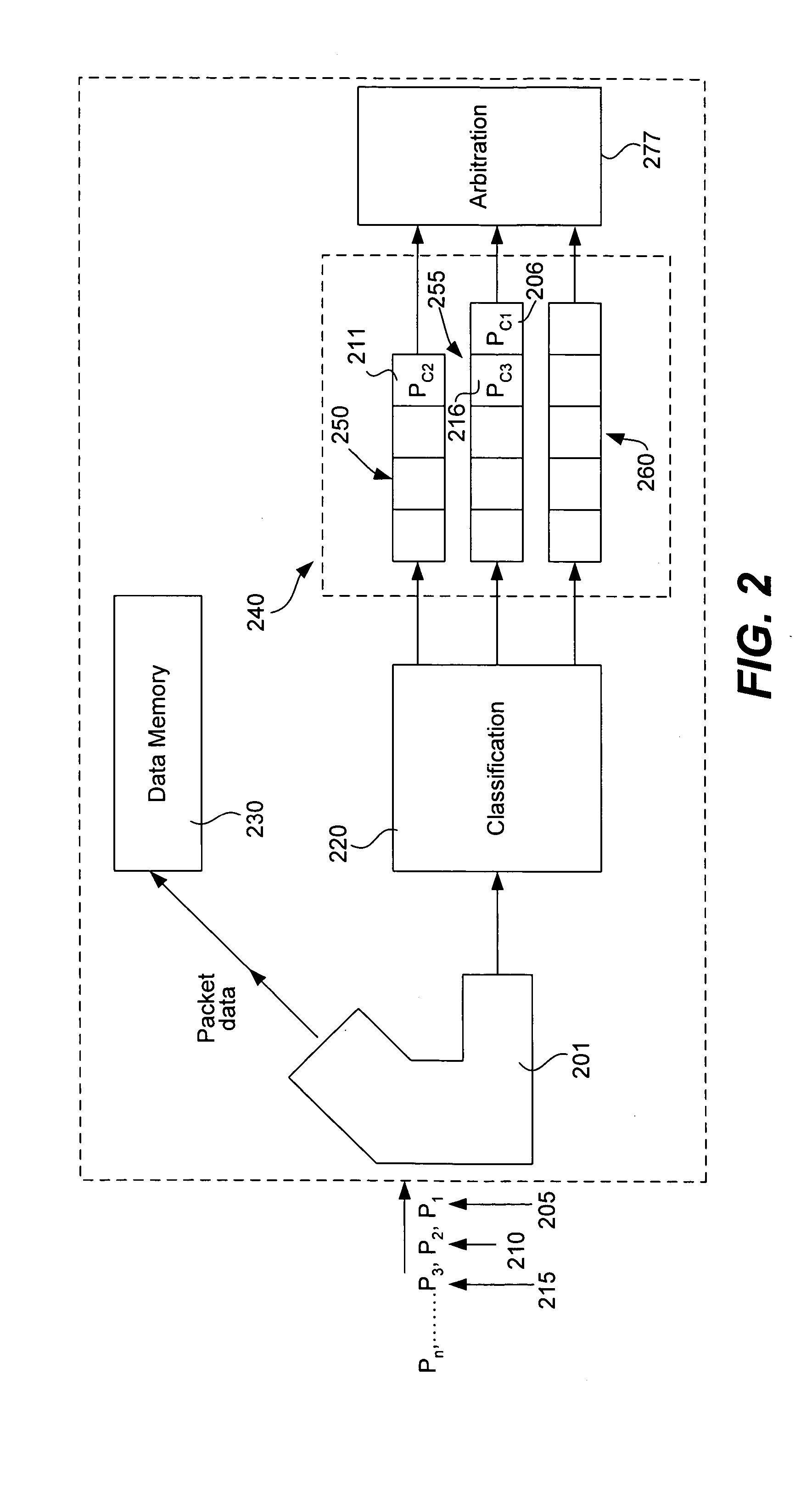
[0034]FIG. 2 illustrates a series of packets arriving at device 200, which is a network device in this example. After the packets arrive at port 201, they are classified by classification engine 220, which may be implemented in software, hardware or firmware. For example, each packet may be sorted according to control information such as its destination, its source, its priority, payload type, etc.

[0035] After the classification step, control information for each packet is assigned to a different one of the queues in array 240. Each of the queues in array 240 may be, e.g., a first-in, first-out (“FIFO”) buffer of a microprocessor (e.g., an ASIC). In this example, control information 206 for packet 205 is stored at the head of queue 255. Control information 216 for packet 215 is also stored in queue 255. Control information 211 for packet 210 is stored at the head of queue 250.

[0036] However, other packet information (e.g., the payload) that may require significantly more memory ca...


PUM


Abstract

Methods and devices are provided for the efficient allocation and deletion of virtual output queues. According to some implementations, incoming packets are classified according to a queue in which the packet (or classification information for the packet) will be stored, e.g., according to a “Q” value. For example, a Q value may be a Q number defined as {Egress port number ∥∥ Priority number∥∥ Ingress port number}. Only a single physical queue is allocated for each classification. When a physical queue is empty, the physical queue is preferably de-allocated and added to a “free list” of available physical queues. Accordingly, the total number of allocated physical queues preferably does not exceed the total number of classified packets. Because the input buffering requirements of Fibre Channel (“FC”) and other protocols place limitations on the number of incoming packets, the dynamic allocation methods of the present invention result in a sparse allocation of physical queues.

Description

BACKGROUND OF THE INVENTION [0001] 1. Field of the Invention [0002] This invention relates generally to network management and specifically relates to controlling traffic flow in network devices. [0003] 2. Description of Related Art [0004] In digital communications systems, data are transmitted between processing devices over a network. In such networks, data are typically sent from one computer to another through network devices such as hubs, routers, bridges and / or switches interconnected by data links. [0005] Network devices have ports that send and receive data, commands, etc. (hereinafter, “data”) to and from the data links. Although this disclosure will mainly refer to data sent in the form of packets, the present invention applies to any addressable entities, including but not limited to datagrams, cells, etc. Accordingly, the terms “packet,”“frame,”“cell,” etc., will be used synonymously herein. [0006] Within a single network device, packets are accepted at ingress ports, tr...

Claims


Application Information

Patent Timeline
Patent Type & Authority Applications(United States)
IPC IPC(8): H04L12/56
CPCH04L47/6215H04L49/30H04L49/9047H04L49/90H04L49/3045
Inventor HOFFMAN, ROBERTKLOTH, RAYMOND J.FULLI, ALESSANDRO
Owner CISCO TECH INC
Why Eureka
Try Eureka