Supercharge Your Innovation With Domain-Expert AI Agents!

Communication network using code division multiplexing technology

Inactive Publication Date: 2005-03-03
OKI ELECTRIC IND CO LTD
View PDF3 Cites 11 Cited by
  • Summary
  • Abstract
  • Description
  • Claims
  • Application Information

AI Technical Summary

Benefits of technology

[0012] An object of the present invention is to provide a technology which can raise a bandwidth use efficiency of a communication network using code division multiplexing.

Problems solved by technology

Therefore, the costs relating to the network architecture rise.
However, in this case, the components used in the optical wavelength division multiplexing are highly expensive, and so the costs relating to network architecture rise.
However, in this case, bandwidth use efficiency becomes poor, due to the need for a channel for achieving synchronization between the terminals carrying out P2P communications.
For this reason, the costs relating to the network architecture rise.

Method used


Image

  • Communication network using code division multiplexing technology
  • Communication network using code division multiplexing technology
  • Communication network using code division multiplexing technology

Examples


first embodiment

[0027] First Embodiment

[0028] A first embodiment of the present invention is described with reference to FIG. 1 to FIG. 7. The present invention is a example in which the present invention is applied to a LAN.

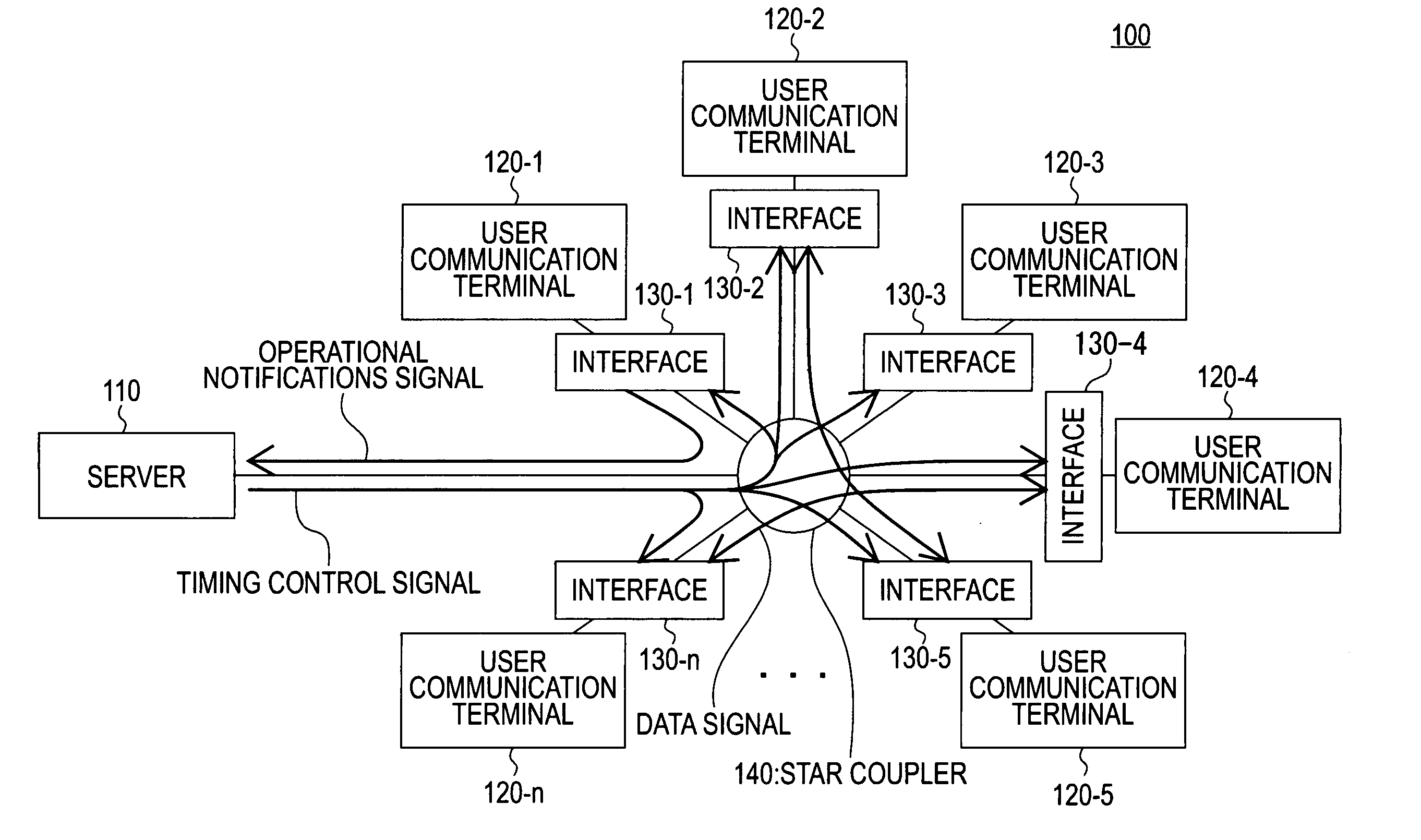
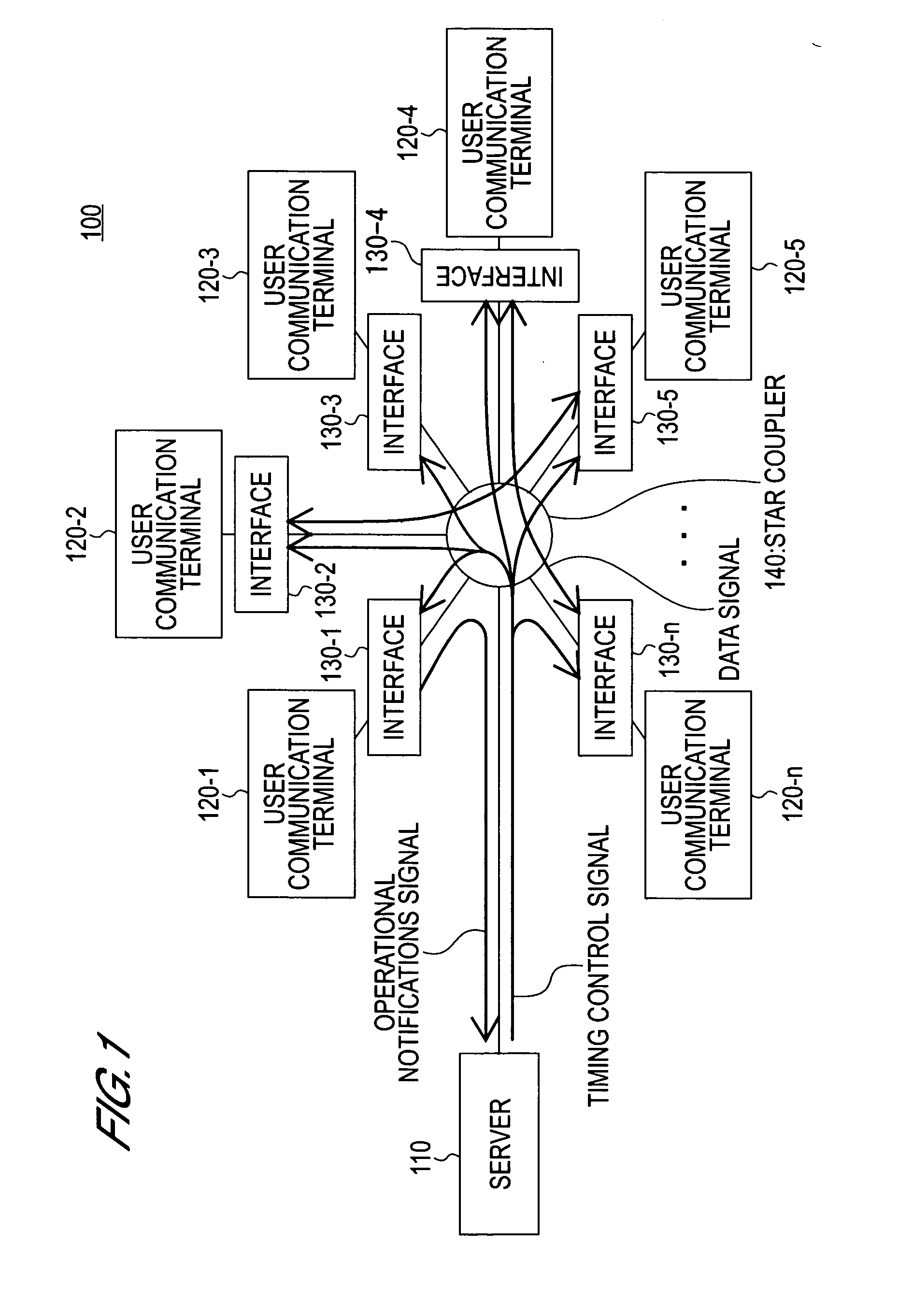
[0029]FIG. 1 is a general diagram showing an approximate view of the overall composition of a peer-to-peer communication system relating to the present embodiment. As shown in FIG. 1, the peer-to-peer communication system 100 according to the present embodiment comprises one server 110, a plurality of user communication terminals 120-1-120-n, a plurality of communication terminal interfaces 130-1-103-n, and one star coupler 140.

[0030] The server 110 is a management device for performing timing control for peer-to-peer communications. Accordingly, the server 110 encodes a timing control signal and outputs it constantly to all of the interfaces 130-1-130-n. In addition, the server 110 receives an encoded operational notifications signal from the interfaces 130-1-130-n. In this ...

second embodiment

[0095] Second Embodiment

[0096] Next, a second embodiment of the present invention is described by using FIG. 8 to FIG. 10. The present invention is a example in which the present invention is applied to a LAN.

[0097] The network 800 relating to the present embodiment transmits connection request between the peer-to-peer communication interfaces, by using broadcast communication technology.

[0098]FIG. 8 is a conceptual diagram showing an approximate view of the general composition of a peer-to-peer communication network relating to the present embodiment. As shown in FIG. 8, the peer-to-peer communications network 800 according to the present embodiment comprises a plurality of user communication terminals 810-1-810-n, a plurality of peer-to-peer communication interfaces 820-1-820-n, and one star coupler 830. The network 800 according to the present embodiment does not comprise a server.

[0099] The communication terminals 810-1-810-n are communication terminals used by users, and are...


PUM


Abstract

A communication network which can use communication bandwidth effectively. Spreading codes of a first and a second code length are assigned for every communication terminal interfaces connected to the same communication network. The spreading codes of the first code length are used for data communications. The spreading codes of the second code length are used for the control communications between the interfaces and the sever. The interfaces and the server receives mixed signals of the data and the control signals. When the received signals are decoded using the spreading code of the first code length, control signal components became equal to or lower than the noise level. When the received signals are decoded using the spreading code of the second code length, data components became equal to or lower than the noise level. Therefore, the interfaces and the server can extract one of these signal components.

Description

BACKGROUND OF THE INVENTION [0001] 1. Field of the Invention [0002] The present invention relates to a communication network using code division multiplexing technology. The present invention can be applied to a communication network which performs peer-to-peer communications, for example. [0003] 2. Description of Related Art [0004] Conventionally, peer-to-peer communication is known as one mode of using the Internet and other similar networks. Peer-to-peer may also be written as “P2P”, and is a communication system whereby information can be exchanged directly between a plurality of user communication terminals, via the Internet and other similar networks. [0005] As is already known, technologies for connecting a user communication terminal to the Internet include, for example, ADSL (Asymmetrical Digital Subscriber Line), ATM-PON (Asynchronous Transfer ModePassive Optical Network), LAN (Local Area Network), or the like. The following references are amongst those which disclose com...

Claims


Application Information

Patent Timeline
IPC IPC(8): H04J13/00H04B1/7073H04B7/005H04B7/216H04B7/26H04B10/272H04J14/00H04L12/44
CPCH04W52/383H04B7/2628
Inventor KASHIMA, MASAYUKIMATSUNO, KAZUHIKO
Owner OKI ELECTRIC IND CO LTD
Features
  • R&D
  • Intellectual Property
  • Life Sciences
  • Materials
  • Tech Scout
  • Unparalleled Data Quality
  • Higher Quality Content
  • 60% Fewer Hallucinations
Learn More