
Automated method for producing improved orthodontic aligners

a technology of automatic production and aligner, applied in the field of orthodontics, can solve the problems of one-piece unsightly appliances, human error in the process of direct (manual) bonding, and drop of conventional procedures used in the past,

Active Publication Date: 2005-03-03
HILLIARD JACK KEITH
View PDF23 Cites 201 Cited by
  • Summary
  • Abstract
  • Description
  • Claims
  • Application Information

AI Technical Summary

Problems solved by technology

When technology-driven changes occur within a specialized field, some of the conventional procedures routinely used in the past may be rendered unnecessary by the technological innovation and are dropped.
Orthodontists and their staff understand that the accuracy with which orthodontic brackets are positioned on the teeth largely determines the quality of the case when finished, and it is well known that human error is always involved in the process of direct (manual) bonding.
They were generally bulky, one-piece unsightly appliances, as shown for example in U.S. Pat. No. 3,724,075.
In contrast, a manually-formed series of progressive aligners are usually limited to treating only sub-objectives of a patient's treatment plan.
An example of the utility of Thermo-Pliers in augmenting aligner-based therapy involves a common problem faced by orthodontists which is the difficulty encountered in trying to rotate a tooth.
Normally, the positional bias of the aligner, referred to above as an out-of-register relationship between the tooth-receiving socket formed in the aligner relative and the actual living tooth will produce force levels that are not fully capable of correcting the position of a tooth in terms of rotation.
Rotations, as opposed to torqueing or tipping-type corrections are relatively difficult to achieve using aligners.
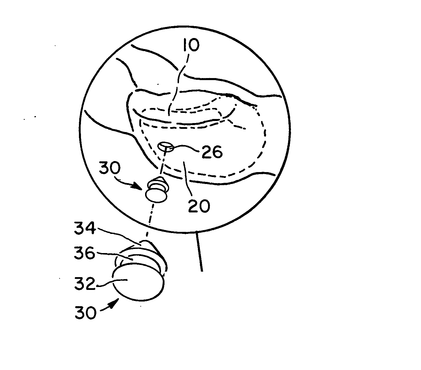
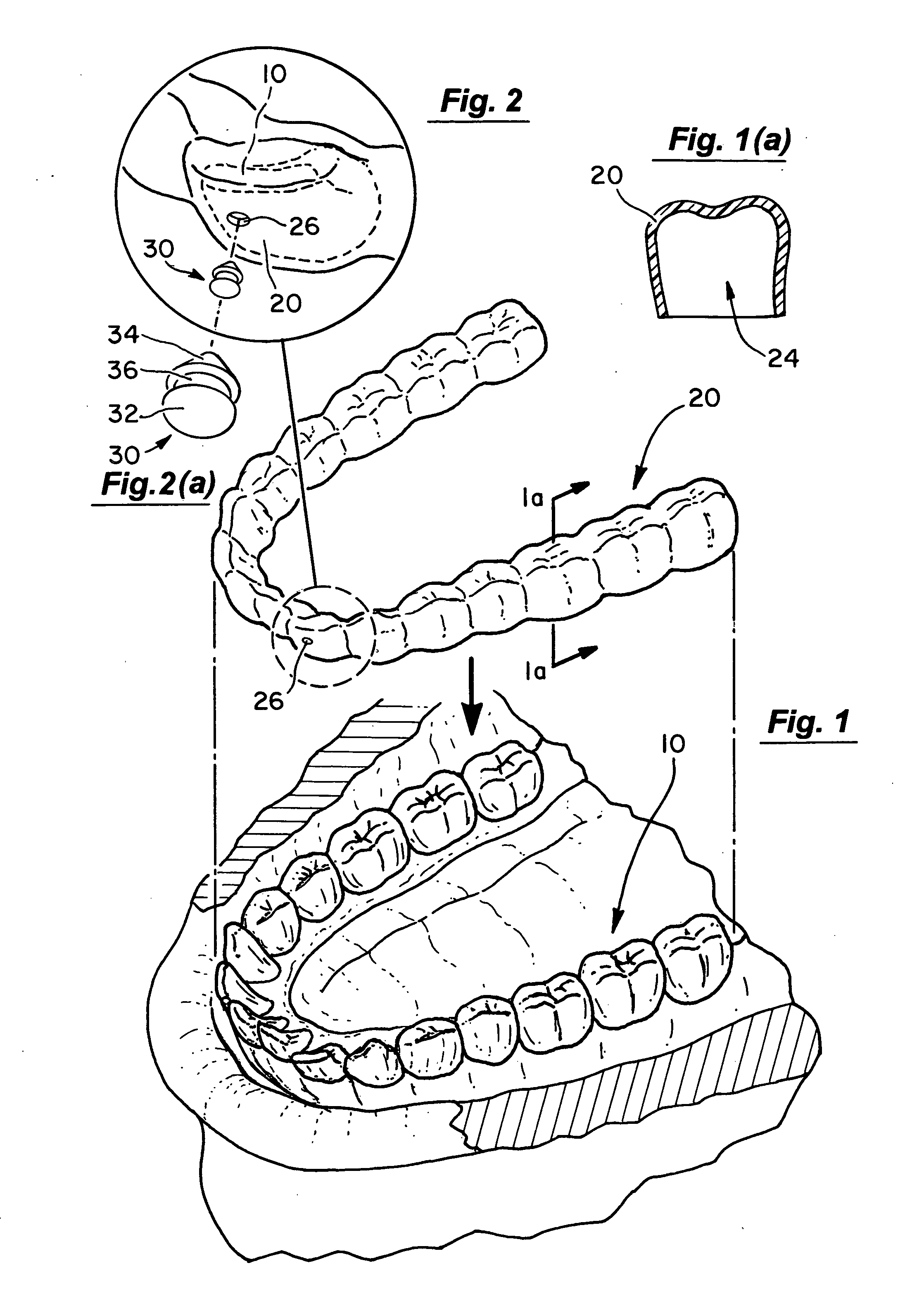
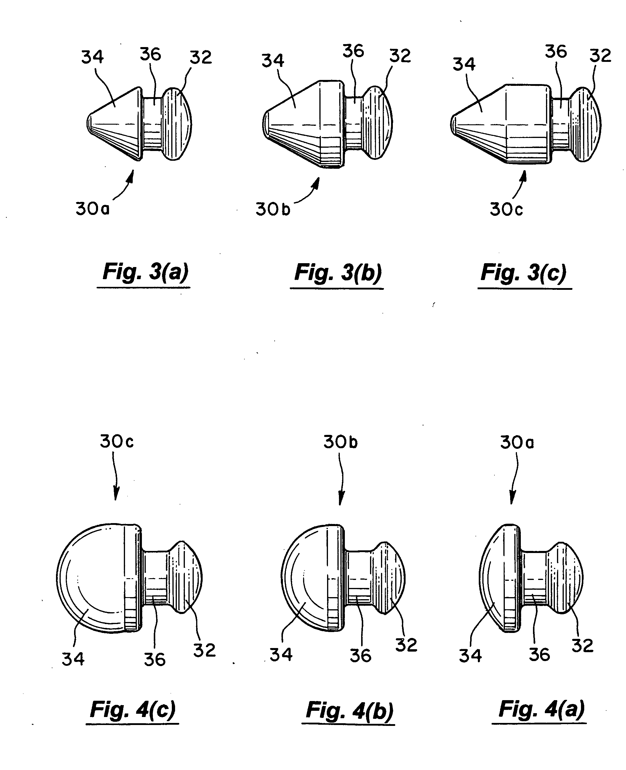
Importantly, note that the tack 30 must engage holes pierced through an aligner, but if their inwardly extending portions contact the underlying tooth, undesirable uncontrolled tooth movement can occur.

Method used


Image

  • Automated method for producing improved orthodontic aligners
  • Automated method for producing improved orthodontic aligners
  • Automated method for producing improved orthodontic aligners

Examples


Embodiment Construction

FIG. 16 is a flowchart providing a general overview of the present invention. To summarize, the present invention is a methodology to produce orthodontic aligners using a CAD system to modify a digital model of the patient's oral anatomy to incorporate features that accommodate attachment of aligner auxiliaries to the completed aligner(s). The present invention represents a convergence of the various advances made in aligner-based orthodontic treatment as may be accomplished by a CAD technician in the setting of a commercial orthodontic service center.

Initially, the relevant portions of the patient's oral anatomy are scanned to create a digital model in a format suitable for viewing and manipulation via a CAD system. As previously discussed, impressions of at least a portion of the patient's dental anatomy can be taken in the orthodontist's office using alginate, PVS or other conventional dental impression materials. These impressions are then used to make conventional stone models...


PUM


Abstract

A method for producing orthodontic aligners uses a CAD system to modify a digital model of the patient's oral anatomy to incorporate features that accommodate attachment of aligner auxiliaries to the completed aligner(s).

Description

BACKGROUND OF THE INVENTION 1. Field of the Invention The present invention relates generally to the field of orthodontics. More specifically, the present invention discloses a method for producing improved orthodontic aligners. 2. Background of the Invention Like many areas involving the delivery of healthcare, the field of dentistry is currently involved in a process of rapid change in what has until recently been considered conventional practice. Such changes are taking place in many fields and are often the result of, and are driven by the integration of new computer-based digital technologies, which tend to become the core of powerful new methodologies. In the dental specialty of orthodontics, for example, the process of laser scanning and the three-dimensional imaging of a patient's teeth and then the manipulation of the virtual tooth positions within a computer-aided-design (CAD) environment is an example. Commercial orthodontic service centers have emerged that provide n...

Claims


Application Information

Patent Timeline
IPC IPC(8): A61C7/00
CPCA61C7/002A61C7/00B33Y80/00
Inventor HILLIARD, JACK KEITH
Owner HILLIARD JACK KEITH
Learn More