

Orthodontic repositioning appliances having improved geometry, methods and systems
- Summary
- Abstract
- Description
- Claims
- Application Information
AI Technical Summary
Benefits of technology
Problems solved by technology
Method used
Image

Examples
Embodiment Construction
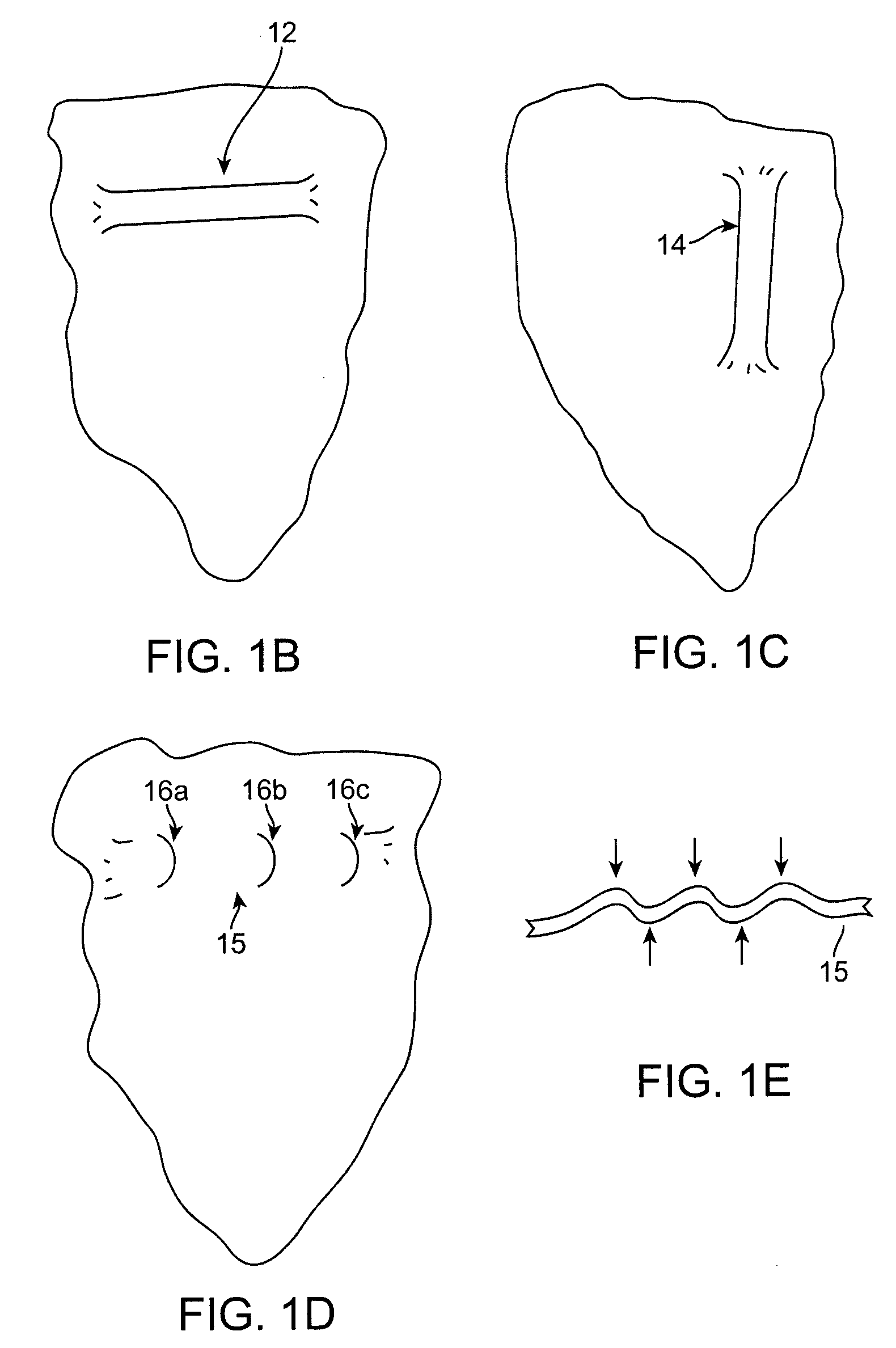
[0029]The invention described herein describes systems and methods including orthodontic appliances having geometries designed to provide more precise control of the forces and moments applied to a tooth, thereby providing better control of the type of tooth movement desired while avoiding unwanted movements, such as unwanted tipping. Appliances according to the present invention can be designed to include certain “shaped features”, such as shaped protrusions (e.g., ridges, dimples, etc.) positioned in a tooth receiving cavity, incorporated into appliance design and structure.
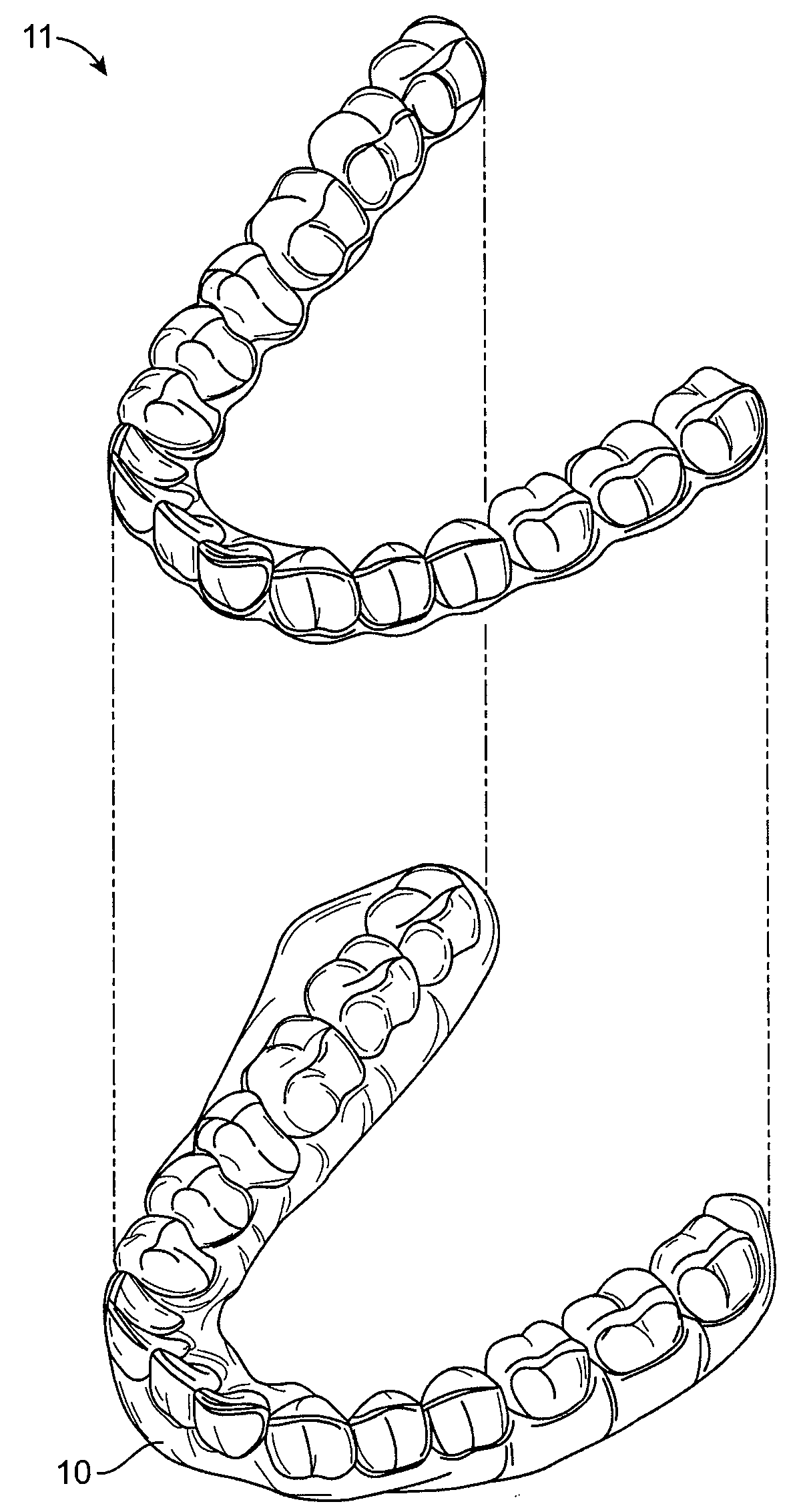
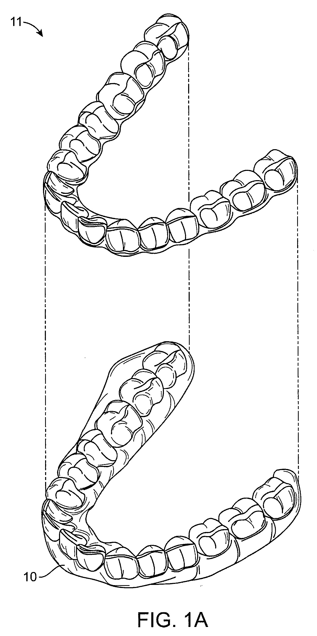
[0030]Appliances having teeth receiving cavities that receive and reposition teeth, e.g., via application of force due to appliance resiliency, are generally illustrated with regard to FIG. 1A. As illustrated, FIG. 1A shows one exemplary adjustment appliance 10 which is worn by the patient in order to achieve an incremental repositioning of individual teeth in the jaw 11. The appliance can include a shell (e.g....
PUM
 Abstract
Description
Claims
Application Information