
Dental implant and device with a dental implant

Inactive Publication Date: 2001-05-08
STRAUMANN HLDG AG +1
View PDF16 Cites 182 Cited by
  • Summary
  • Abstract
  • Description
  • Claims
  • Application Information

AI Technical Summary

Benefits of technology

The first and second interstices of the dental implant according to the invention make it possible to fasten to one and the same implant secondary and / or superstructural components of optionally different configuration, which, depending on their configuration, are able to assume only a single rotational position defined by the positioning section of the implant, or which can assume a rotational position selected from several possible rotational positions, or whose rotational position is not defined by the positioning section.
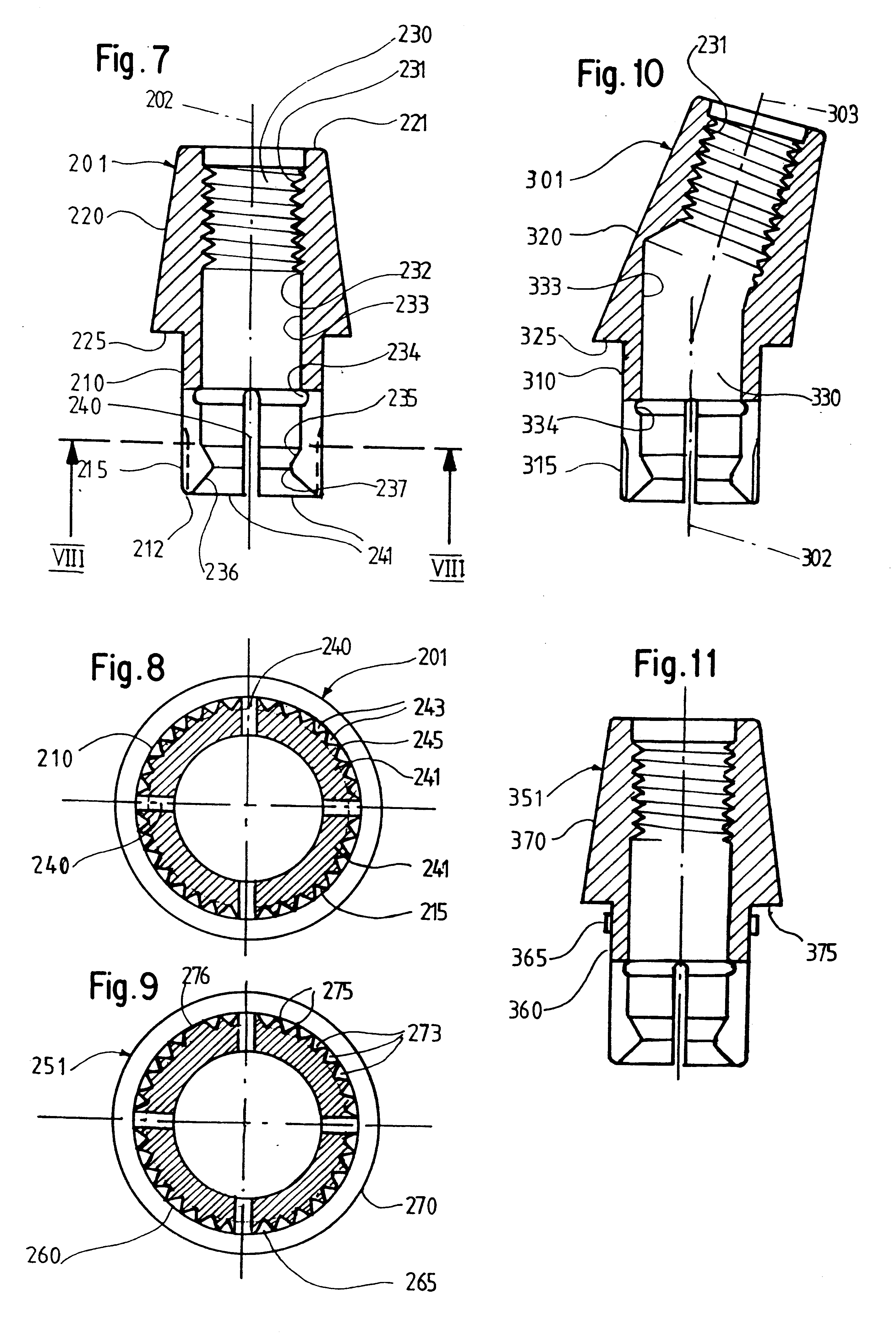
Each interstice in the implant is defined preferably at least partially by flats which are approximately or precisely parallel to a straight line passing radially to the axis through the center of the interstice in question, or form with such a straight line an angle of at most 60.degree. and preferably no more than 45.degree.. Furthermore, each interstice has, for example, two substantially planar lateral surfaces. The interstices can be approximately V-shaped in cross section, or they can have also a base surface and be approximately U-shaped. The interstices can furthermore be substantially completely curved, and form an arc, for example, which is no more than equal to a semicircle and, for example, smaller than a semicircle. The projection, or every projection, of the secondary part and implant engaging in an interstice has a certain free play, so that in spite of possible manufacturing inaccuracies and in spite of dimensional changes caused by temperature changes, the projection can be inserted easily into the interstice. The free play of a projection, measured tangentially to the above-mentioned pitch circle is preferably made so small that the secondary or superstructural part can be turned back and forth by no more than an angle amounting preferably to no more than 2.degree., or better 1.degree., or even no more than 0.5.degree..
The blind bore of the implant has preferably an internal thread serving for the removable attachment of the secondary part. If the secondary part has a positioning section with a projection or, preferably, a plurality of projections, the secondary part can be releasably fastened to the implant with an external thread which can be screwed into the internal thread of the implant. The fastening means can consist, for example, of a screw with a head urged against a surface of the secondary part, or of a headless screw which can be threaded into the secondary part. The headless screw can then have, in addition to the external thread which can be screwed into the internal thread of the implant, an external thread which can be screwed into an internal thread in the secondary part, and one of the external threads can be right-handed, for example, and the other left-handed, and / or the two external threads can have different pitches. To attach a secondary part to provide positioning, therefore, only a single additional element is needed, namely the said fastening means. If the secondary part, however, has no projection designed to engage a positioning groove in the implant, the secondary part can either also be fastened releasably to the implant, likewise with a separate fastening means of the kind described, or it may be provided with an external thread which can be screwed into the internal thread of the implant and consists, together with the remaining sections of the secondary part, of a one-piece body. Possibly a secondary part can also be provided which is fastened to the implant, not by screwing, but one which when used is first inserted releasably into the hole in the implant, and then, when it must no longer be removed, it is cemented or glued in the bore in the implant. The bore in the implant can then nevertheless have an internal thread so that the same type of implant can also be used to accommodate a threaded secondary part. If desired, however, the internal thread can be omitted from the implant. The secondary part can be joined securely and free of micromovements to the implant by the above-described screwing, cementing or gluing methods, so that in a physiological environment, it will not loosen due to micromovements.

Problems solved by technology

Also, the secondary part is glued into the implant and accordingly can no longer be removed from it.
So this implant does not permit any precise setting of the rotational position of a secondary part reaching into the bore in the implant.
This, combined with the small dimensions of the guiding portion, results in a great danger that the prosthesis under stress will perform small movements--so-called micromovements--with respect to the implant, and thus a failure of the dental treatment is caused.

Method used


Image

  • Dental implant and device with a dental implant
  • Dental implant and device with a dental implant
  • Dental implant and device with a dental implant

Examples


Embodiment Construction

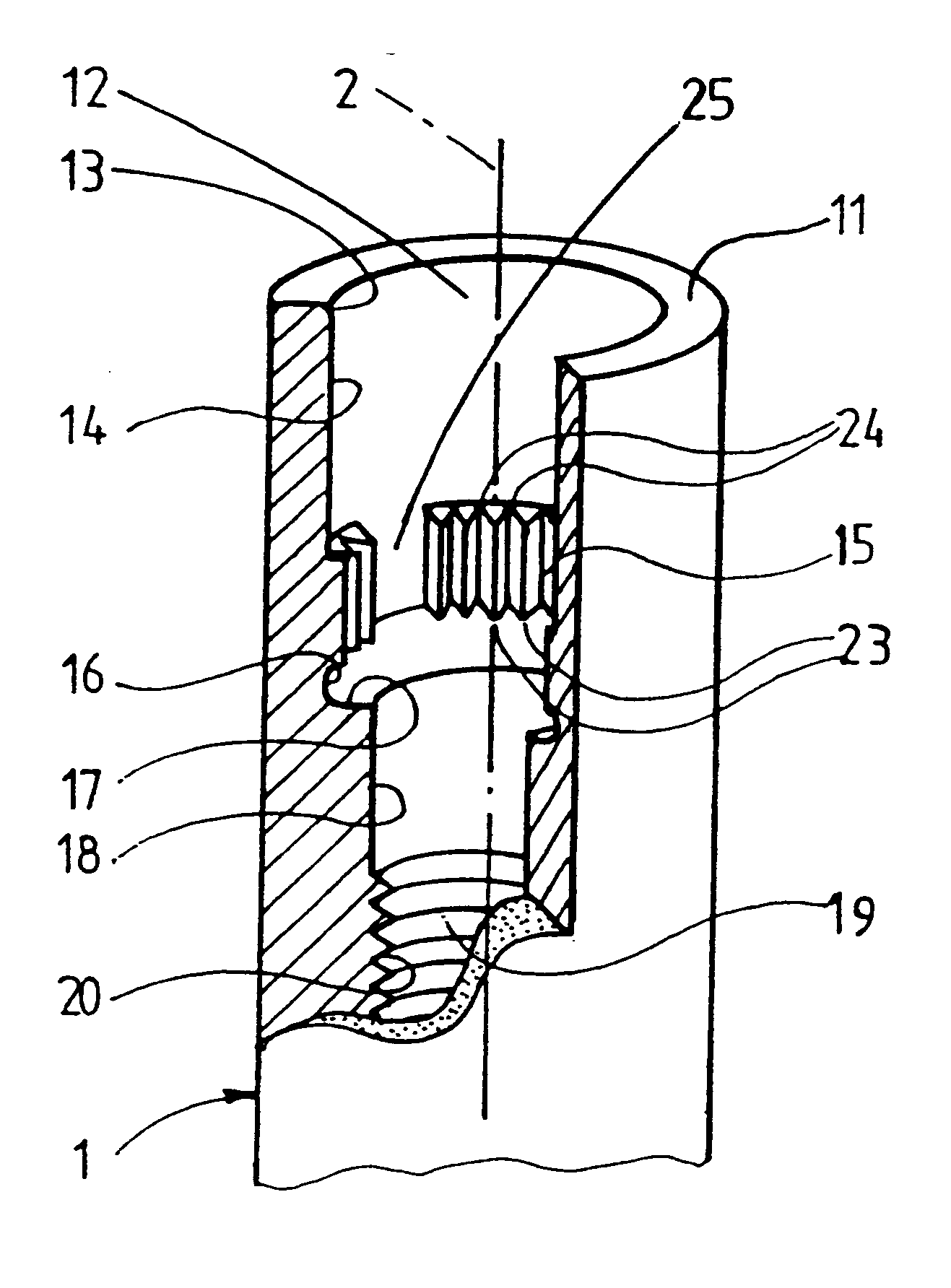
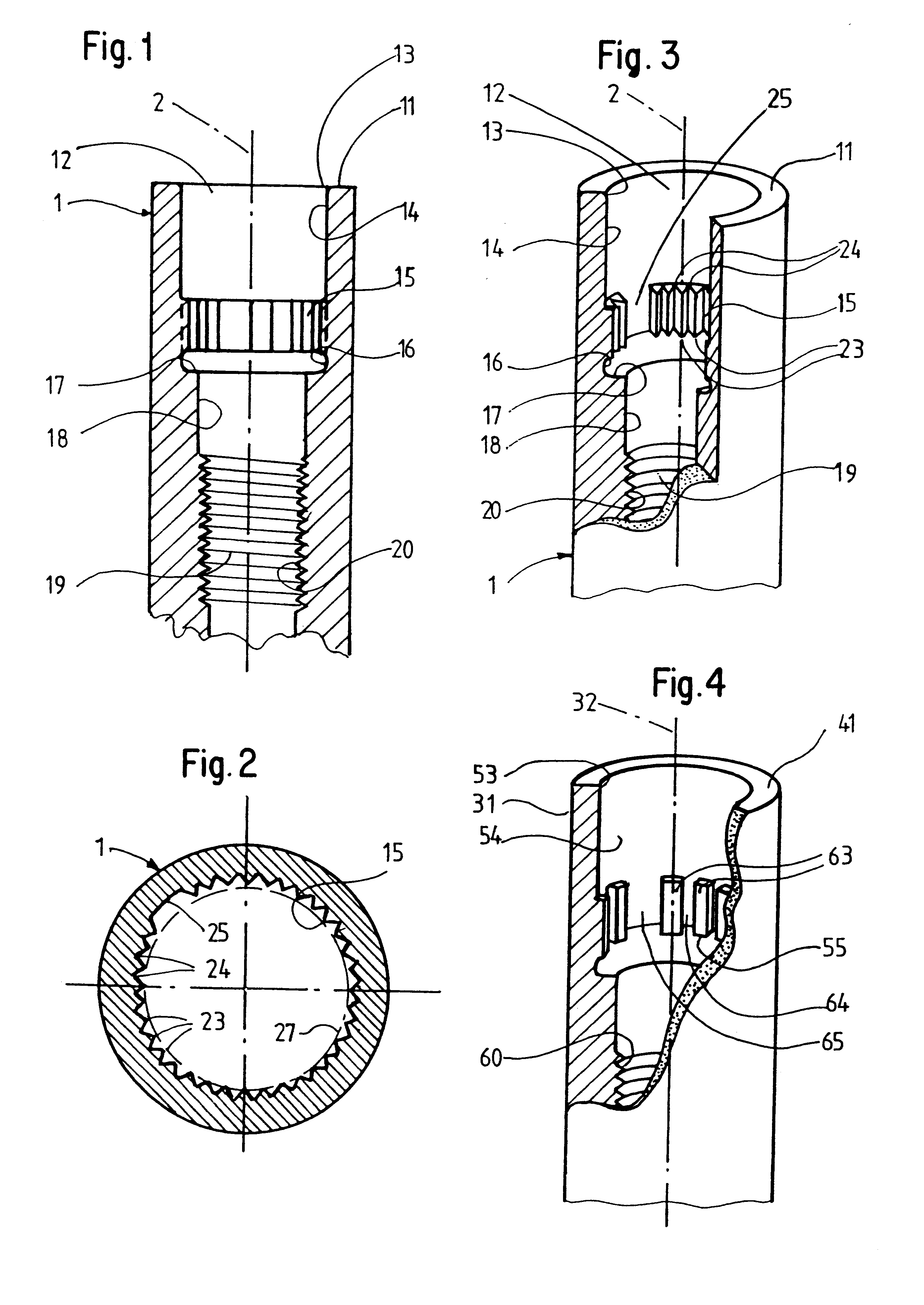
The dental implant 1 represented in FIGS. 1 to 3 is elongated as well as generally rotationally symmetrical with an axis 2 and has at the top a cylindrical, smooth circumferential surface 10. The lower part of implant 1, which is not seen in FIGS. 1 and 3, can be configured, for example, in any known or novel manner, and have, for example, a smooth cylindrical exterior or a screw thread. Also, the unseen lower part of the implant can have, for example, a cavity open at the bottom or a solid cross section at the bottom end.

The implant 1 has at the upper end an implant shoulder 11 which is formed by a planar annular surface radial to the axis 2. The implant is provided with a stepped blind bore 12 generally coaxial with the axis 2. This bore has a mouth 13 situated at the upper end of the implant and surrounded by the inner margin of the annular surface forming the shoulder 11, and downward from the latter a cylindrical main section 14, a positioning section 15, a short, generally cyl...


PUM


Abstract

The invention relates to a dental implant which has an axis and a hole with a positioning section. Said positioning section has projecting parts and intermediate spaces distributed alternately, one after the other, along the periphery. Said intermediate spaces comprise several first intermediate spaces which create a division, and a second, wider intermediate space. A secondary and / or supplementary structural part can be attached in the implant, said part having a connecting section which extends into the hole. Said connecting section can have projecting parts for engaging in the intermediate spaces of the implant, and can be configured in such a way that it can be fixed to the implant in several different rotated positions or a single rotated position. The secondary and / or supplementary structural part can also be produced without projecting parts of the type mentioned, so that it can be screwed into the implant.

Description

The invention relates to a dental implant. The implant can be used as an intraosteal implant and can be inserted into the bone of an upper or lower jaw. A secondary part can be fastened to the implant to serve for holding, and / or for the construction of, a dental prosthesis, i.e., a prosthesis with a single artificial tooth or a number of artificial teeth. The implant can furthermore serve to hold a special superstructure forming, for example, an entire single artificial tooth.STATE OF THE ARTA device disclosed in DE 41 27 849 A has an implant and a secondary or holding part. The implant has an axial blind bore with a polygonal section. The secondary part has a polyhedral section fitting into the polyhedral section of the blind bore. The polyhedral sections are configured as dodecahedral sections, so that the secondary part can be set selectively in any one of twelve positions, i.e., can be joined non-rotationally to the implant. In many cases, however, it would be desirable if the ...

Claims


Application Information

Patent Timeline
IPC IPC(8): A61C8/00
CPCA61C8/005A61C8/0066A61C8/0068A61C8/0069A61C8/0054
Inventor SUTTER, FRANZ
Owner STRAUMANN HLDG AG
Learn More