Electrical connector with latching system

Inactive Publication Date: 2005-03-03
HON HAI PRECISION IND CO LTD
View PDF10 Cites 13 Cited by
  • Summary
  • Abstract
  • Description
  • Claims
  • Application Information

AI Technical Summary

Benefits of technology

[0008] A main object of the present invention is to provide an electrical con

Problems solved by technology

However, the lock release buttons lack of support and/or securement within the connector and easily to loose away from the housing, thus causing inoperation of the system due to breakage or damage of the components.
In addition, such a latching mechanism lacks of enough stretch force

Method used


Image

  • Electrical connector with latching system
  • Electrical connector with latching system
  • Electrical connector with latching system

Examples


Embodiment Construction

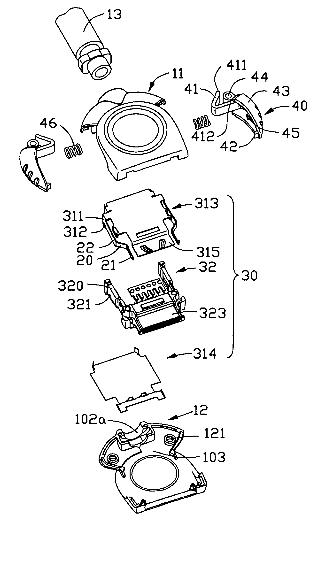
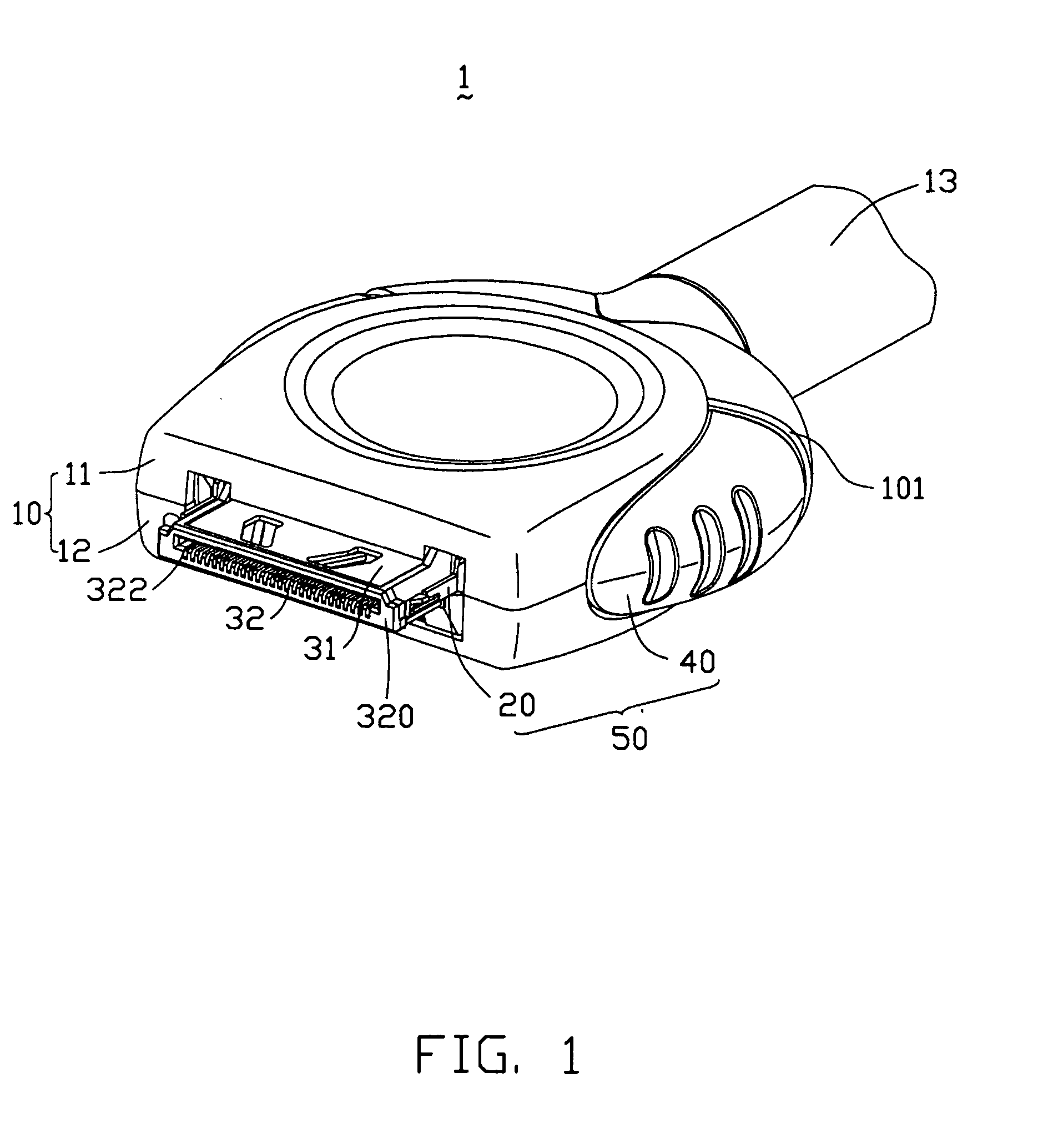
[0018] Referring to the drawings in greater detail, and first to FIG. 1, the invention is embodied in an electrical connector, generally designated 1, which is an input / output (I / O) shielded connector specifically adapted for mating with a complementary connector. The electrical connector 1 comprises a dielectric cover 10, a terminal module 32, a metallic shield 31 shielding the terminal module 32 and a pair of latching mechanisms 50 positioned in opposite sides of the dielectric cover. However, it should be understood that various features of the invention are equally applicable for other types of connectors, as will be fully understandable from the following detailed description.

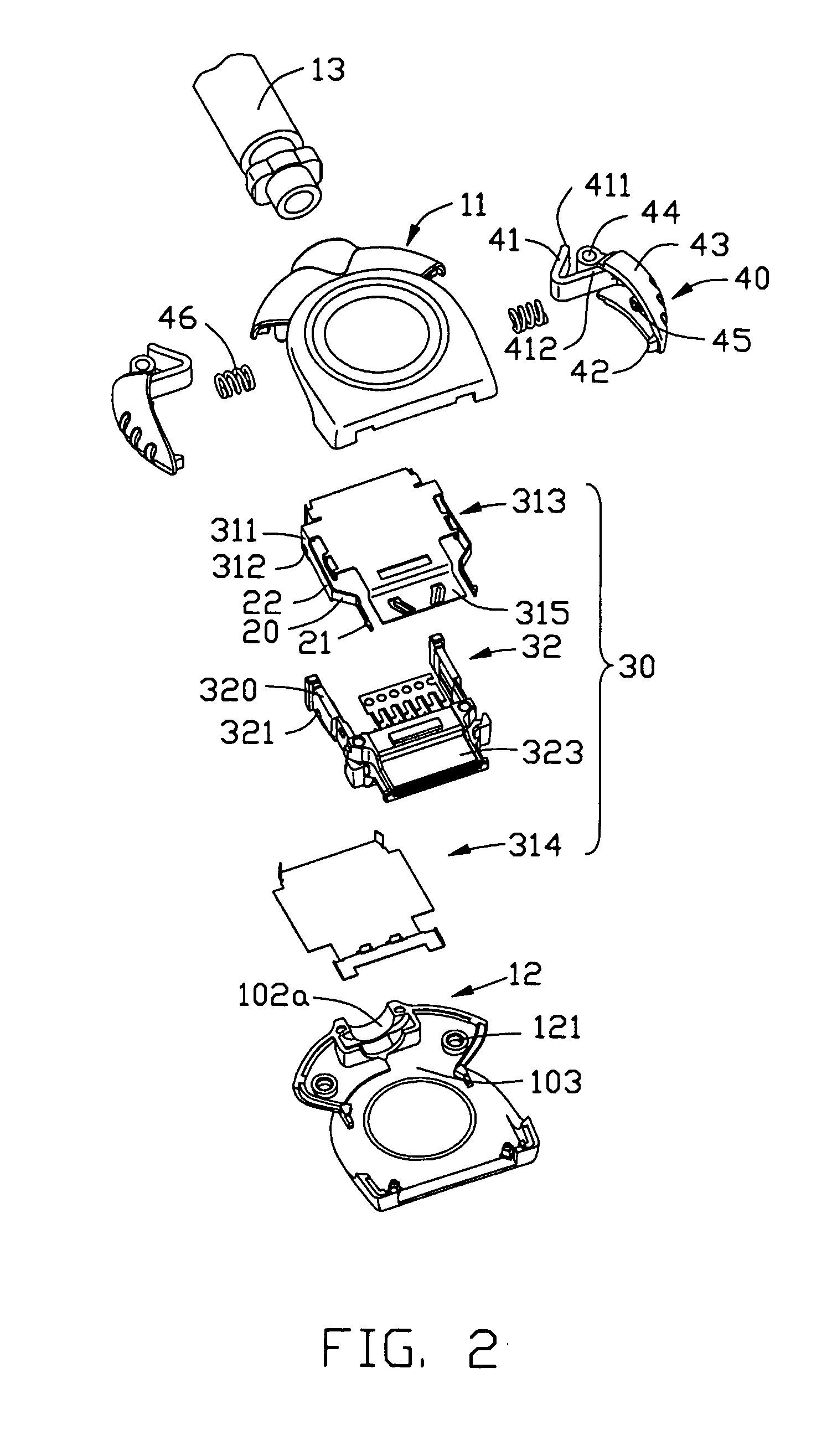
[0019] Referring to FIGS. 2 and 3 in conjunction with FIG. 1, the cover 10 is formed by a pair of split cover halves, namely an upper cover 11 and a lower cover 12. The lower cover 12 is coupled to the upper cover 11, thereby forming a receiving space 103 therebetween for receiving the terminal module 32 ...


PUM


Abstract

An electrical connector (1) includes a terminal module (32), a metallic shield (31) shielding the terminal module, an outer dielectric cover (10) substantially surrounding the shield and a button (40) attached to the cover. The terminal module includes a mating portion (323) having a number of conductive terminals (322) exposed therein. The shield provides a resilient latching beam (20) at a front portion thereof. The latching beam includes a driving portion (22) and an outwardly extending latching portion (21) adjacent to the mating portion. The cover has an inwardly projecting post (111). The button includes an operating base (43) and an actuator arm (41) being pivotally movable about the post to push the button outwardly.

Description

CROSS-REFERENCE TO RELATED APPLICATION [0001] This application is related to U.S. patent application Ser. No. ______ entitled “ELECTRICAL CONNECTOR WITH LATCHING SYSTEM” and assigned to the common assignee.BACKGROUND OF THE INVENTION [0002] 1. Field of the Invention [0003] The present invention generally relates to the art of electrical connectors and more particularly, to a electrical connector provides means for latching an electrical connector with a complementary electrical connector or other connecting device. [0004] 2. Description of the Prior Art [0005] In high speed and other telecommunicating and computer applications, shielded input / output (I / O) connectors have been used at connection interfaces between computers and telecommunication networks. It is important to lock or latch two mating connectors to one another for ensuring proper and complete interconnection of the connector terminals and to further ensuring ongoing connections of the connectors. There are a plurality o...

Claims


Application Information

Patent Timeline
IPC IPC(8): H01R13/627H01R13/658H01R13/66
CPCH01R13/6275H01R13/6658H01R13/65802H01R13/6582
Inventor LI, XIAO LILIN, YI SHENG
Owner HON HAI PRECISION IND CO LTD
Why Eureka
Try Eureka