
Paint roller with extendable handle

a technology of extension poles and paint rollers, which is applied in the direction of portable power tools, manufacturing tools, carpet cleaners, etc., can solve the problems of difficult assembly and movement around the work site, relative cost alternatives, and easy situations

Active Publication Date: 2005-03-10
NOVA WILDCAT SHUR LINE LLC
View PDF7 Cites 28 Cited by
  • Summary
  • Abstract
  • Description
  • Claims
  • Application Information

AI Technical Summary

Benefits of technology

"The present patent relates to painting accessories and, more specifically, to paint rollers and extension poles. The technical effects of the patent include providing a more secure and easy-to-use attachment between the roller and the pole, as well as a more efficient and secure attachment between the handle and the roller. Additionally, the patent addresses the issue of multiple threads and pitches for different manufacturers of accessories, and provides a solution for easily adapting to different thread configurations. The patent also describes various examples of extension poles and collet assemblies for painting accessories, which can be used to extend the reach of the user and access hard-to-reach areas."

Problems solved by technology

While effective, they are relatively expensive alternatives, and are relatively difficult to assemble and move about a work site.
Furthermore, a dangerous situation can easily arise in which a user leans to far away from the ladder and could possibly tip over and injure him or herself.
If the user is moving back and forth between a situation wherein the extension pole is needed and not needed, he or she is therefore confronted with attaching and detaching the pole from the paint roller a number of times during the painting process.
This necessarily slows the work flow and can be frustrating to the user.
While effective, this may undesirably dirty the hand of the user.

Method used


Image

  • Paint roller with extendable handle
  • Paint roller with extendable handle
  • Paint roller with extendable handle

Examples


Embodiment Construction

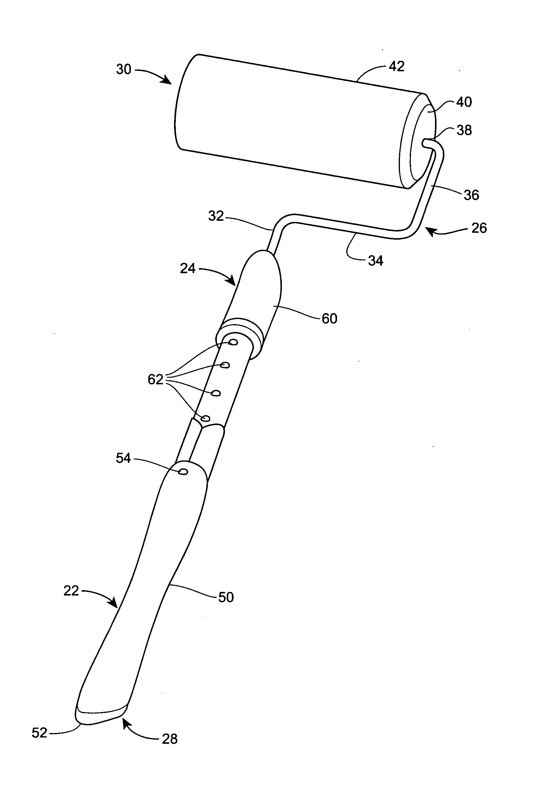
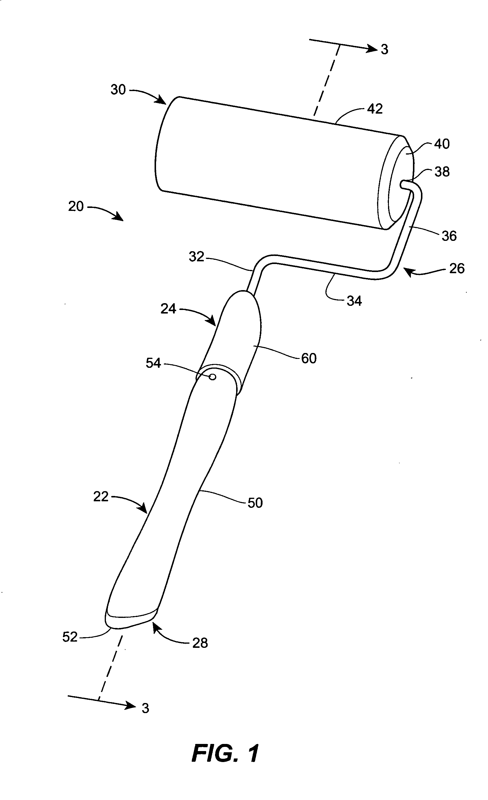
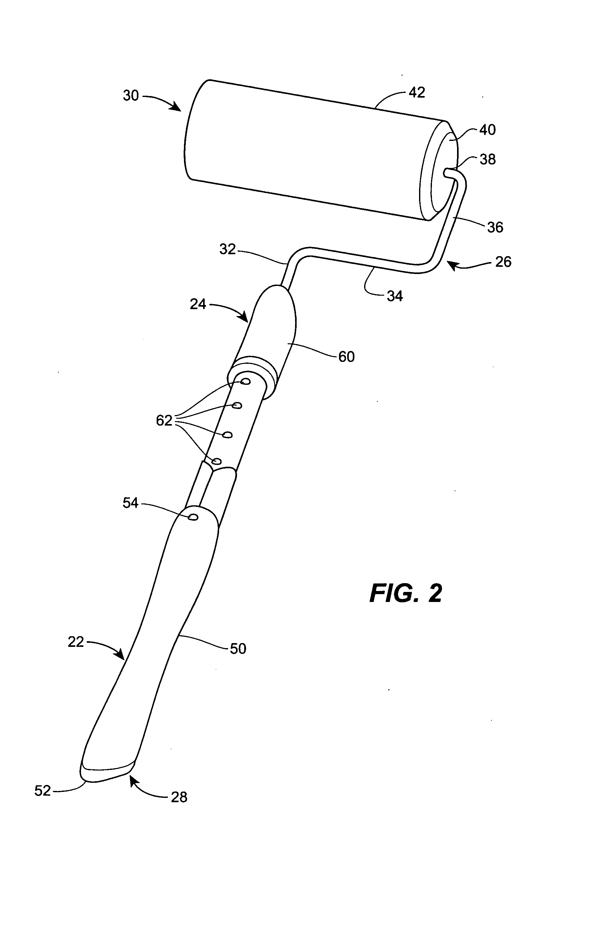
[0032] Referring now to the drawings, and in particular to FIGS. 1 and 2, a paint applicator 20 is disclosed. The paint applicator 20 includes a first handle section 22, a second handle section 24, and an implement section 26. The second handle section 24 can telescope within the first handle section 22, and the implement section 26 can telescope within the second handle section 24 such that the implement section 26 and second handle section 24 can move from a retracted position, shown in FIG. 1, to an extended position, shown in FIG. 2. The paint applicator 20 includes a proximal end 28 and a distal end 30.

[0033] The implement section 26 includes a main leg 32, an offset leg 34, a spacer leg 36, and a mounting leg 38. Rotatably disposed on the mounting leg 38 is a mounting spool 40 that is configured to support a paint roller 42. The paint roller 42 can be mounted on the mounting spool 40 by an interference fit such that the paint roller 42 does not slip on the mounting spool 40 w...


PUM


Abstract

An extendable handle for a paint applicator includes an first shaft having a distal end and a proximal end and a second shaft with a distal end and a proximal end and which is telescopically disposed within the first shaft. A guide block is disposed on the second shaft and defines a curved channel. A third shaft has a distal end and a proximal end and is telescopically disposed within the second shaft. An advancement strip has a first end connected to the distal end of the first shaft and a second end connected to the proximal end of the third shaft and is disposed through the curved channel of the guide block. The advancement strip can both push and pull the third shaft relative to the second shaft.

Description

FIELD OF THE DISCLOSURE [0001] The present disclosure relates to painting accessories and, more specifically, relates to paint rollers and extension poles. BACKGROUND OF THE DISCLOSURE [0002] Painting apparatuses generally called paint rollers are known in which a cylindrical paint brush is fitted on to a roller. The roller is rotatably connected to a handle such that a user can roll the cylindrical paint brush along a wall surface to transfer paint from the paint brush to the wall surface. In the most common design, the handle is only one to two feet long. [0003] In many painting applications, it is necessary for the user to access hard-to-reach locations. For example, with interior painting of walls and the like, a user typically can not reach the ceiling of the room simply with an out-stretched arm and a typical paint roller. Accordingly, ladders and scaffolding are commonly employed in such situations. While effective, they are relatively expensive alternatives, and are relative...

Claims


Application Information

Patent Timeline
Patent Type & Authority Applications(United States)
IPC IPC(8): B05C17/02B25G1/04
CPCB05C17/0205Y10T16/473B25G1/04
Inventor GOULET, MATTHEW G.
Owner NOVA WILDCAT SHUR LINE LLC
Learn More