Connecting rod device for plugging PCB (Printed Circuit Board) plate

A technology of PCB board and connecting rod device, which is applied to the components, coupling device, connection and other directions of the connecting device to achieve the effect of simple structure and good operability

Active Publication Date: 2012-10-31
HUAWEI TECH CO LTD
View PDF5 Cites 43 Cited by
  • Summary
  • Abstract
  • Description
  • Claims
  • Application Information

AI Technical Summary

Benefits of technology

This patented connexion between an electronic component called computer motherboard (PC) or mainframe card(s), which needs 2 dimensional plugging/unplugged connections with another type of components like memory devices attached thereto. It allows these connectors to work together smoothly without any problems caused when they are turned off due to power failures. Overall this design ensures stable operation even during extreme conditions such as power loss.

Problems solved by technology

This technical problem addressed by this patented technology relates to improving the maintenance ability and functionality of electronic systems while still allowing them to connect with external components like printers without requiring any extra steps during installation.

Method used


Image

  • Connecting rod device for plugging PCB (Printed Circuit Board) plate
  • Connecting rod device for plugging PCB (Printed Circuit Board) plate
  • Connecting rod device for plugging PCB (Printed Circuit Board) plate

Examples


no. 5 approach

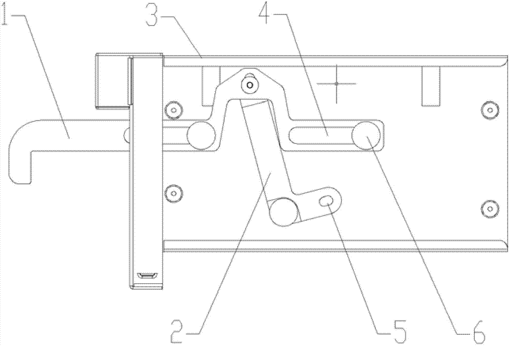
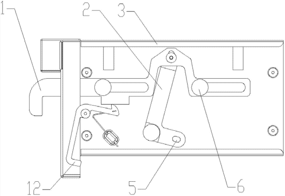
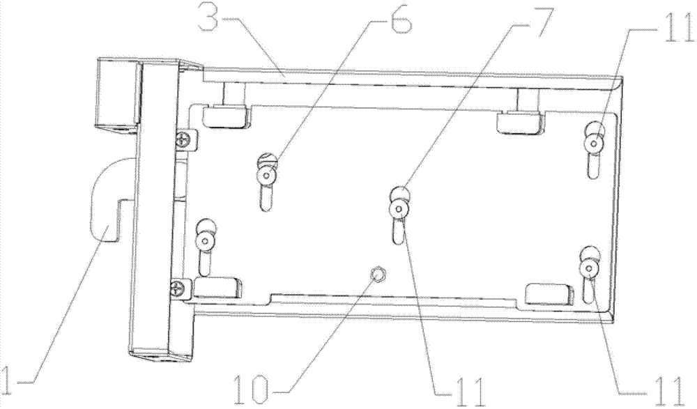
[0051] Fifth embodiment of the present invention: the fixing hole 5 is arranged on the carrier plate 8 instead of being arranged on the second end of the swing rod 2 , and the corresponding second fixing pin 10 is arranged on the second end of the swing rod 2 instead of being arranged on the carrier plate 8 superior. For other implementation details, reference may be made to other embodiments of the present invention and the preferred or optional solutions introduced therein, and details are not repeated here.

[0052] Corresponding to the fourth and fifth embodiments, the following similar modifications can also be made: there are multiple swing rods 2 , and the swing rods 2 are located on the same side or both sides of the horizontal groove 4 .

[0053] It can be seen that the connecting rod device for plugging and unplugging the PCB board provided by the embodiment of the present invention can drive the swing rod through the pull rod, so as to drive the carrier board to mov...


PUM


Abstract

The invention provides a connecting rod device for plugging a PCB (Printed Circuit Board) plate. The connecting rod device is arranged between a bottom plate and a carrier plate, and the carrier plate is used for fixing the PCB plate. The connecting rod device comprises a pull rod and an oscillating rod, wherein the pull rod is rotatably connected with the oscillating rod, and the pull rod is connected with the bottom plate through a horizontal guide groove and a first fixed pin; the oscillating rod is in an L shape, the first end of the oscillating rod is rotatably connected with the pull rod, the intermediate corner is rotatably connected with the bottom plate, and the second end is fixed with the carrier plate; and the bottom plate is connected with the carrier plate through a third fixed pin. In the invention, the oscillating rod is driven by the pull rod to drive the carrier plate to vertically move so that the pull rod is pushed and pulled under the uninterrupted condition of a system, and therefore, the hot plug of a PCI (Peripheral Component Interconnect) expansion card fixed on the carrier plate and the plug of other PCB plates which need to be subjected to two-dimensional plug are realized.

Description


Claims


Application Information

Patent Timeline
Owner HUAWEI TECH CO LTD
Why Eureka
Try Eureka